
Driver circuit for the direct modulation of a laser diode

a laser diode and driver circuit technology, applied in the direction of lasers, laser details, electrical apparatus, etc., can solve the problems of laser diodes with high-speed pulsed signals, failure mechanisms, and difficulties, and achieve the effect of low amplitude noise and high fidelity

Inactive Publication Date: 2011-11-17
INSTITUT NATIONAL D'OPTIQUE
View PDF7 Cites 14 Cited by
  • Summary
  • Abstract
  • Description
  • Claims
  • Application Information

AI Technical Summary

Benefits of technology

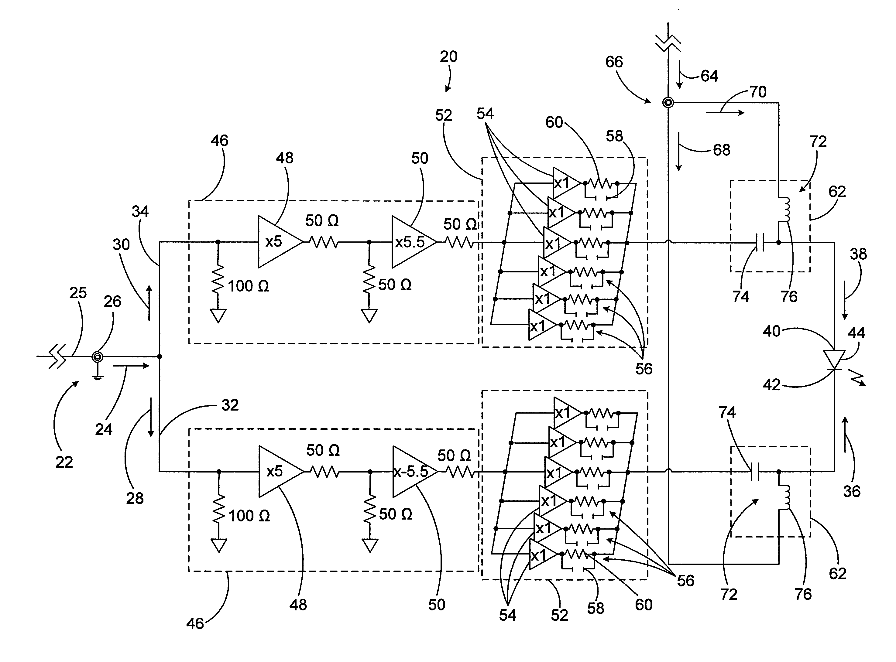
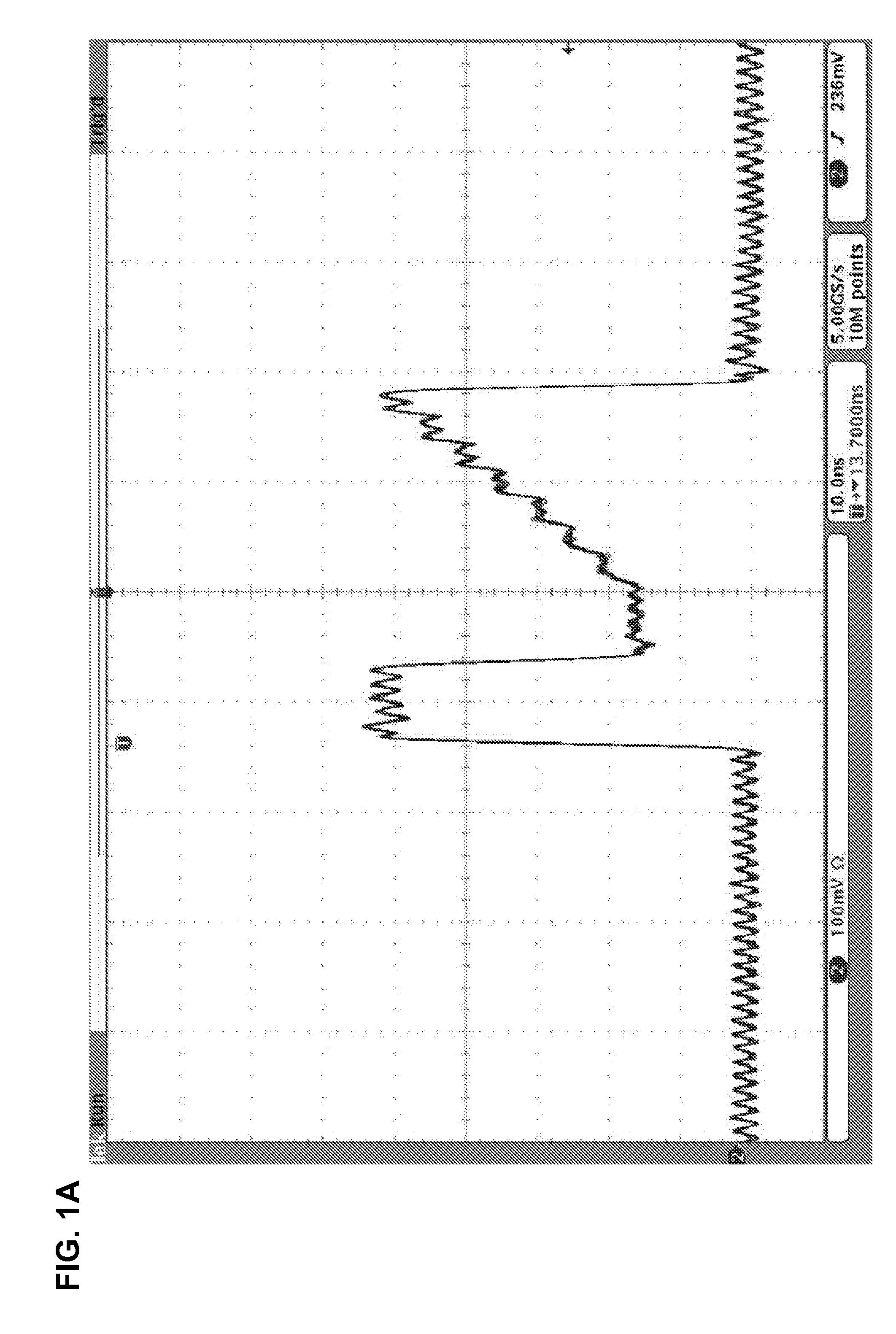
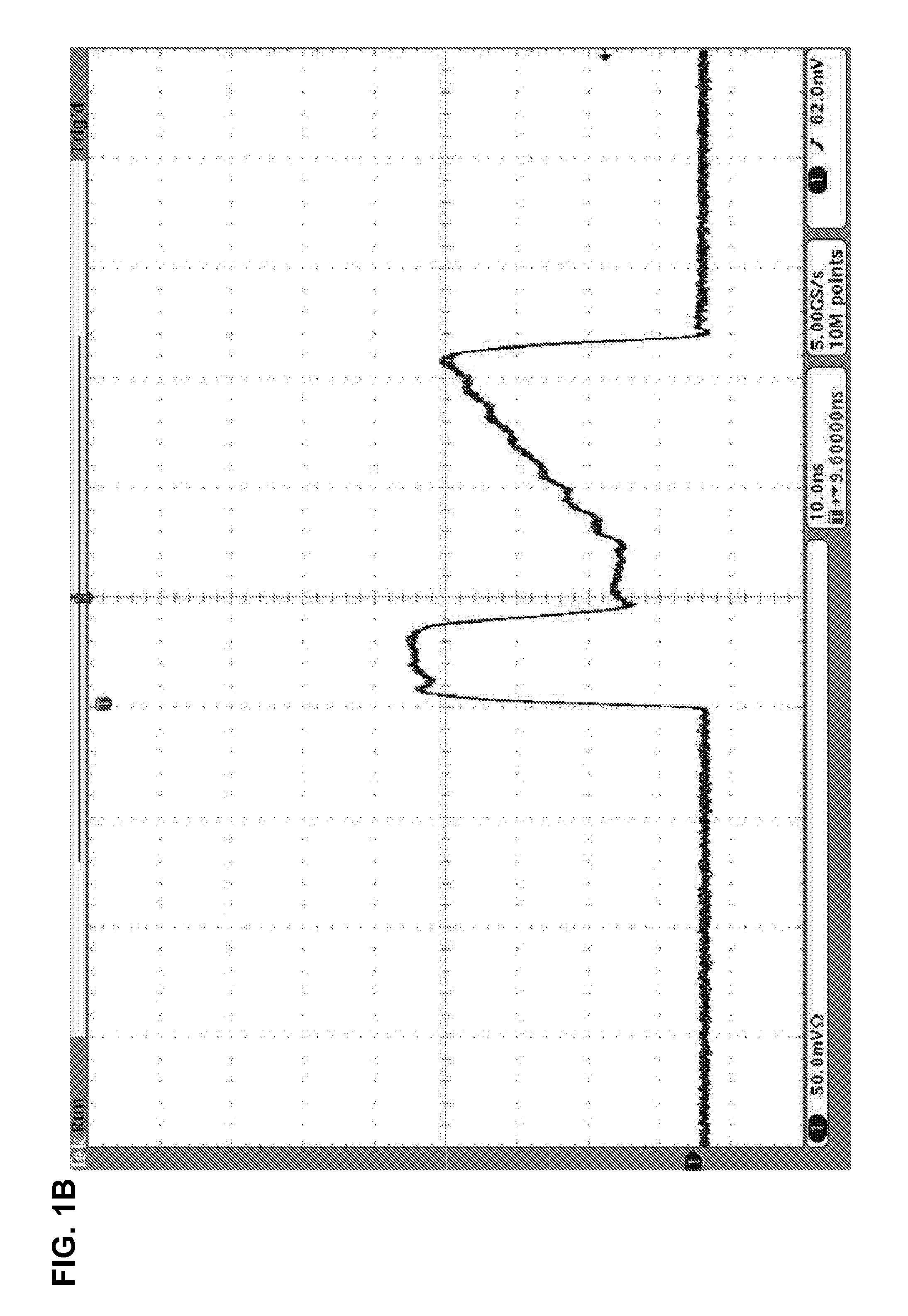
[0019]Advantageously, embodiments of the present invention provide high-speed laser diode driving circuits which are capable of adapting the electric signal provided by a pattern generator, such as a low voltage signal transmitted in a coaxial cable with a typical impedance of 50Ω, to drive a laser diode. The output of the laser diode is an optical signal that reproduces the electric signal from the pattern generator with high fidelity and low amplitude noise.

Problems solved by technology

If the pulse energy is too low, then the link could be only partially fused, whereas if the energy is too high the substrate can be damaged, leading to failure mechanisms.
Driving a laser diode with high-speed pulsed signals however represents a real challenge to electronics designers.
For example, difficulties arise if one wants to drive a laser diode with a relatively high current around 1 A or more with very short rise time and fall time, in the range of 1 ns or less.
At these speeds, difficulties such as parasitic inductance and capacitance effects greatly limit the performances of the circuit.

Method used


Image

  • Driver circuit for the direct modulation of a laser diode
  • Driver circuit for the direct modulation of a laser diode
  • Driver circuit for the direct modulation of a laser diode

Examples


Embodiment Construction

[0026]In accordance with one aspect of the present invention, there is provided a driver circuit for providing driving signals to a laser diode, based on a pulsed input signal.

[0027]Preferred embodiments of the invention are particularly adapted for the driving of a high-speed laser diode, such as used for microprocessing applications and the like. The expression “laser diode” is understood to refer to a laser with a semiconductor-based gain media. The laser diode may for example be embodied by a 14-pin butterfly packaged diode such as used in the telecommunication industry, but other type of diodes may of course be considered, such as DFB (distributed feedback) laser diodes, DBR (distributed Bragg reflector) laser diodes, external cavity laser diodes with a short cavity (<1 cm) and a wavelength selective feedback element such as a small diffraction grating, for example, seeded Fabry-Perot short cavity laser diodes, Fabry-Perot short cavity laser diode with wavelength selective feed...


PUM


Abstract

A driver circuit for a laser diode provides drive signals to the electrodes of the laser diode based on a pulsed input signal. An input receives the pulsed input signal and launches it into an amplification stage which preferably includes dual amplifiers, a buffering stage and a biasing stage. The output of the laser diode is an optical signal that reproduces the pulsed input signal with high fidelity and low amplitude noise. In one embodiment, the input separates the pulsed input signal into two signal components, launched in respective inverting and non-inverting branches which each include successive amplification, buffering and biasing stages.

Description

FIELD OF THE INVENTION[0001]The present invention relates to the field of laser diodes and more particularly concerns a driver circuit for driving a laser diode based on a pulsing input signal.BACKGROUND OF THE INVENTION[0002]Seeding a pulsed fiber laser oscillator with a directly modulated laser diode is a simple and cost-effective way of generating high energy, high peak power optical pulses with high stability. In material processing applications where a single pulse is used to process a given structure, such as severing links for memory repair, it is important to keep the pulse energy within a predetermined range. If the pulse energy is too low, then the link could be only partially fused, whereas if the energy is too high the substrate can be damaged, leading to failure mechanisms. It is therefore highly desirable to have optical pulses that have very high energy and amplitude stability. In a MOPA configuration (Master Oscillator Power Amplifier), as any undesirable features pr...

Claims


Application Information

Patent Timeline
IPC IPC(8): H01S3/10H01S3/00
CPCH01S5/0428H01S5/06226H01S5/06216
Inventor DESBIENS, LOUISDUCHESNE, FRANCOISJACOB, MICHELLABRANCHE, BRUNOROY, VINCENT
Owner INSTITUT NATIONAL D'OPTIQUE
Learn More