Semiconductor device and method of manufacturing the same
a semiconductor and semiconductor technology, applied in the direction of semiconductor devices, electrical devices, transistors, etc., can solve the problems of reducing the reliability of transistors including oxide semiconductors, and achieve the effects of stable electrical characteristics, less variation in threshold voltage, and favorable electric characteristics
- Summary
- Abstract
- Description
- Claims
- Application Information
AI Technical Summary
Benefits of technology
Problems solved by technology
Method used
Image
Examples
embodiment 1
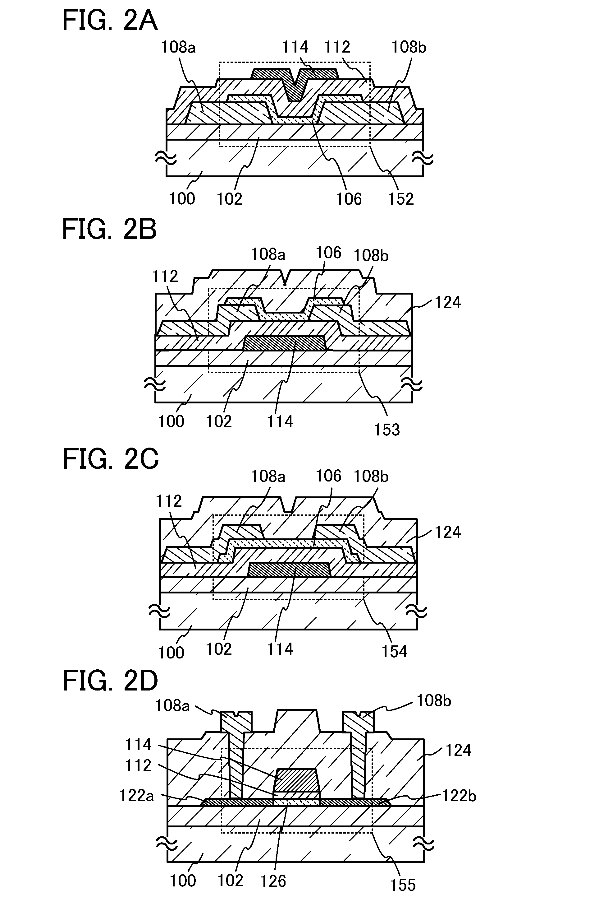
In this embodiment, one embodiment of a semiconductor device and a method for manufacturing the semiconductor device will be described with reference to FIGS. 1A to 1C, FIGS. 2A to 2D, FIGS. 3A to 3E, FIGS. 4A to 4E, FIGS. 5A to 5E, FIGS. 6A to 6E, and FIGS. 7A to 7E.
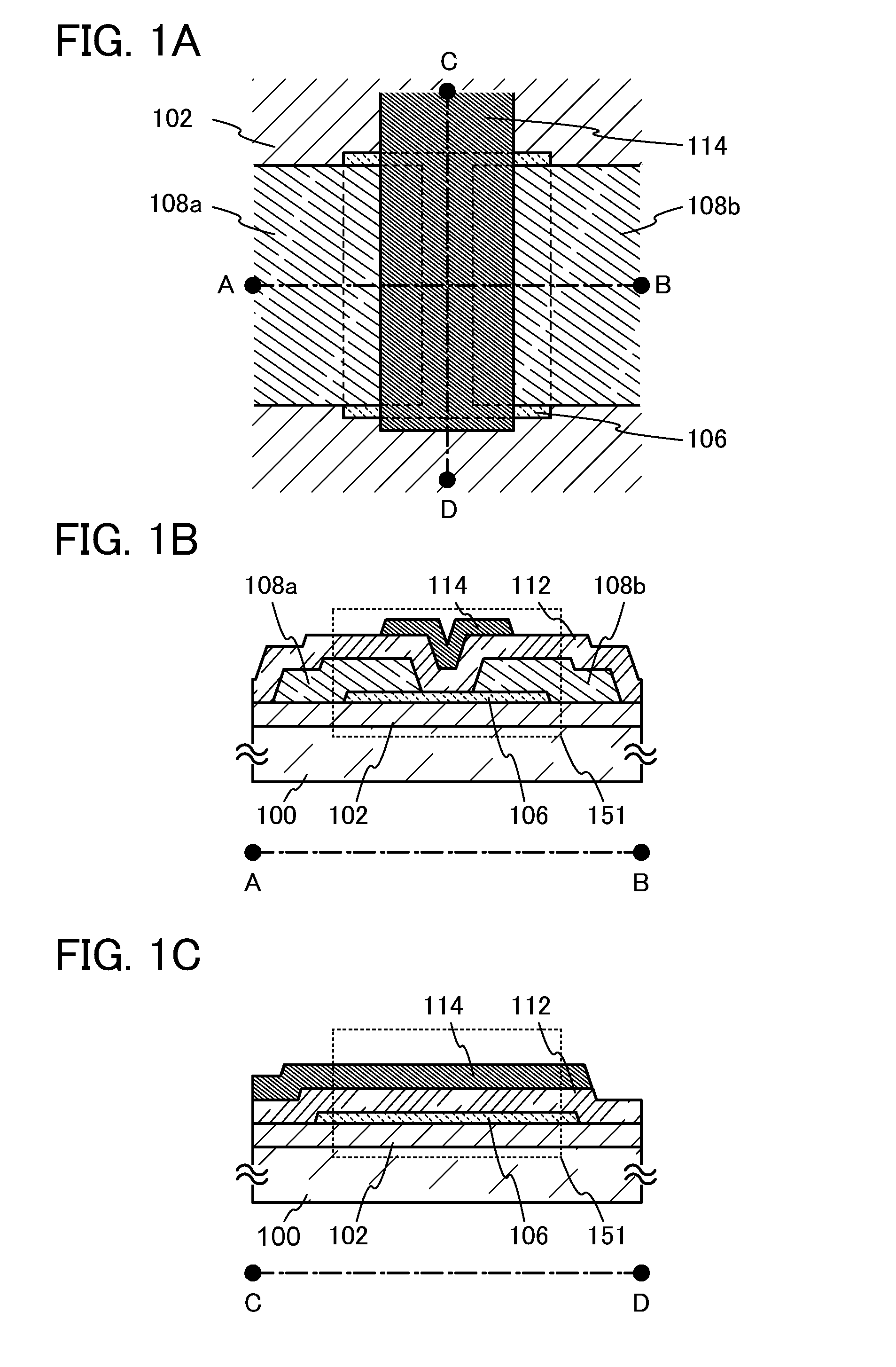
FIGS. 1A to 1C are a top view and cross-sectional views of a transistor 151 which is a top-gate top-contact type as an example of a semiconductor device according to one embodiment of the present invention. Here, FIG. 1A is a top view, FIG. 1B is a cross-sectional view along A-B of FIG. 1A, and FIG. 1C is a cross-sectional view along C-D of FIG. 1A. Note that in FIG. 1A, some of components of the transistor 151 (for example, a gate insulating layer 112) are omitted for brevity.
The transistor 151 in FIGS. 1A to 1C includes a base insulating layer 102, an oxide semiconductor layer 106, a source electrode 108a, a drain electrode 108b, the gate insulating layer 112, and a gate electrode 114 over a substrate 100.
As a materia...
embodiment 2
A semiconductor device (also referred to as a display device) with a display function can be manufactured using the transistor, an example of which is shown in Embodiment 1. Some or all driver circuits including the transistors can be formed over a substrate where a pixel portion is formed, whereby a system-on-panel can be obtained.
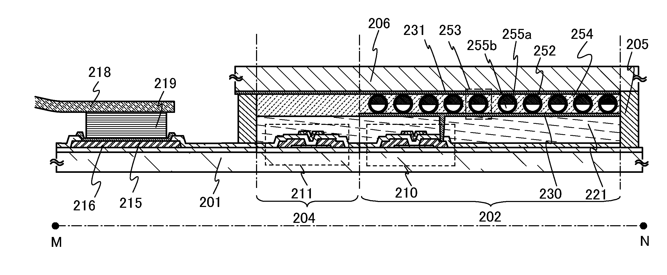
In FIG. 8A, a sealant 205 is provided to surround a pixel portion 202 provided over a first substrate 201, and the pixel portion 202 is sealed with the sealant 205 between the first substrate 201 and a second substrate 206. In FIG. 8A, a scan line driver circuit 204 and a signal line driver circuit 203 each are formed using a single crystal semiconductor layer or a polycrystalline semiconductor layer over a substrate prepared separately, and mounted in a region different from the region surrounded by the sealant 205 over the first substrate 201. Various signals and potentials are supplied to the signal line driver circuit 203 and the scan line driver circ...
embodiment 3
A semiconductor device which is one embodiment of the present invention can be applied to a variety of electronic devices (including game machines). Examples of electronic devices are a television set (also referred to as a television or a television receiver), a monitor of a computer or the like, a camera such as a digital camera or a digital video camera, a digital photo frame, a mobile phone handset (also referred to as a mobile phone or a mobile phone device), a portable game machine, a portable information terminal, an audio reproducing device, and a large-sized game machine such as a pachinko machine. Examples of electronic devices each including the semiconductor device described in the above embodiment are described.
FIG. 12A illustrates a laptop personal computer, which includes a main body 301, a housing 302, a display portion 303, a keyboard 304, and the like. By applying the semiconductor device described in Embodiment 1 or 2, the laptop personal computer can have high re...
PUM
 Abstract
Description
Claims
Application Information
 - R&D
- Intellectual Property
- Life Sciences
- Materials
- Tech Scout
- Unparalleled Data Quality
- Higher Quality Content
- 60% Fewer Hallucinations
Browse by: Latest US Patents, China's latest patents, Technical Efficacy Thesaurus, Application Domain, Technology Topic, Popular Technical Reports.
© 2025 PatSnap. All rights reserved.Legal|Privacy policy|Modern Slavery Act Transparency Statement|Sitemap|About US| Contact US: help@patsnap.com


