Multilayer helical wave filter for MRI applications

a multi-layer helical wave filter and filter technology, applied in the field of implantable medical systems, can solve the problems of overheating of said lead or its associated electrode(s), multiple amputations, and overheating of the associated interface with body tissue,

Inactive Publication Date: 2011-11-24
WILSON GREATBATCH LTD
View PDF2 Cites 34 Cited by
  • Summary
  • Abstract
  • Description
  • Claims
  • Application Information

AI Technical Summary

Benefits of technology

y one dielectric type. In fact, an advantage of the present invention is that different dielectric materials may be used in different areas of the multilayer helical wave filter. For example, one could use one type of dielectric with a specific dielectric constant, for a portion between the first and second helically wound segments, a second dielectric with a different dielectric constant in another portion and even a third dielectric in different portion. This would change the parasitic capacitance and the resonant characteristics of the various sections of the multilayer helical wave filter. In other words, the multilayer helical wave filter could be designed to be resonant at a number of frequencies corresponding to various MRI RF pulsed frequencies and/or their harmonics.
The return connecting segment may extend inside of both the first and second helically wound segments, or the return connecting segment may extend exteriorly of both the first helically wound and second helically wound segments. Further, the connecting segment may be coiled and again routed either exteriorly of the first and second helically wound segments, or inside of both the first and second helically wound segments. The return connecting segment may be straight or curvilinear. Since the induced RF current is reversed in the return segment, it is important that the return connecting segment not be extended between the first helically wound segment and the second helically wound segment.
In various embodiments, one of the helically wound segments is disposed radially inside the other, or the first and second helically wound segments are co-radially disposed about the common longitudinal axis in a side-by-side relationship.
In another embodiment, a third helically wound segment has a first end and a second end and forms a third inductive component. The first, second and third helically wound segments are wound in the same longitudinal direction, wherein a planar surface of the third helically wound segment faces a planar surface of the second helically wound segment. The elongated conductor includes a second connecting segment extending substantially the length o

Problems solved by technology

It has been documented that when this current becomes excessive, overheating of said lead or its associated electrode(s) or overheating of the associated interface with body tissue can occur.
There have been cases of damage to such body tissue which has resulted in loss of capture of cardiac pacemaking pulses or tissue damage severe enough to result in brain damage or multiple amputations, and the like.
There have been reports of latent problems with cardiac pacemakers or other AMDs after an MRI procedure, sometimes occurring many days later.
Moreover, there are a number of papers that indicate that the SAR level is not entirely predictive of the heating that would be found in implanted leads or devices.
It is speculated that SAR level alone is not a good predictor of whether or not an implanted device or its associated lead system will overheat.
The effects of this heating are not readily detectable by monitoring during the MRI.
Such long term heating effects of MRI have not been well studied yet for all types of AMD lead geometries.
There can also be localized heating problems associated with various types of electrodes in addition to tip electrodes.
Variations in the pacemaker lead length and implant trajectory can significantly affect how much heat is generated.
Most experts still conclude that

Method used


Image

  • Multilayer helical wave filter for MRI applications
  • Multilayer helical wave filter for MRI applications
  • Multilayer helical wave filter for MRI applications

Examples


Embodiment Construction

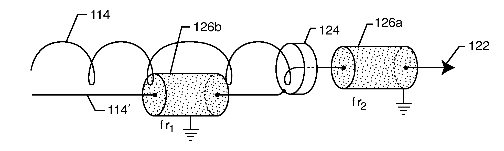
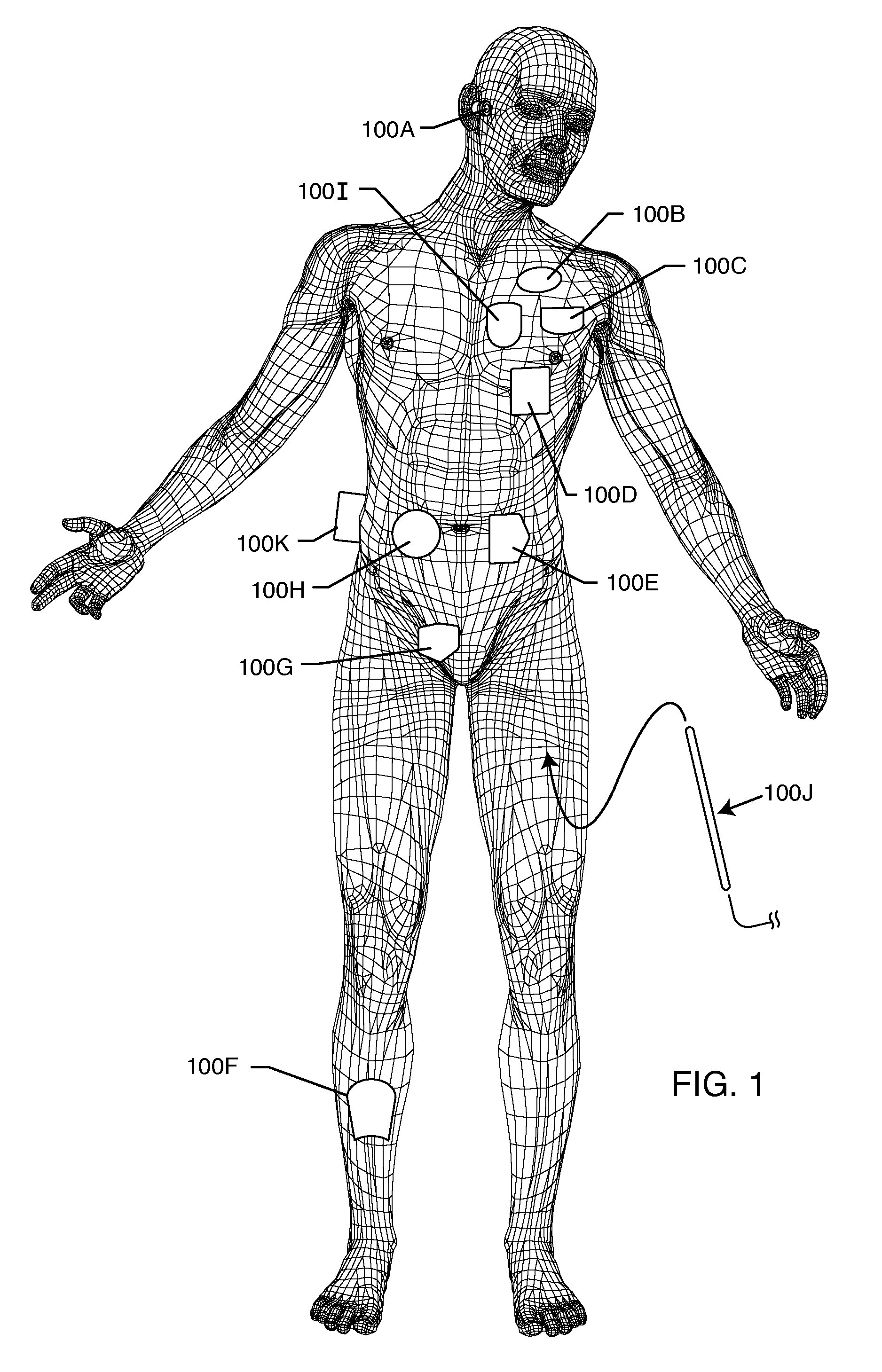
As shown in the drawings for purposes of illustration, the present invention relates to multilayer helical wave filters placed between proximal and distal ends of an implantable lead of an active medical device (AMD). One or more multilayer helical wave filters may be implanted anywhere along the length of implanted leads or electrodes of AMDs. In particular, the multilayer helical wave filter of the present invention presents a very high impedance (which impedes RF current flow) at one or more MRI RF pulsed frequencies. The present invention is particularly important to protect implanted leads from overheating in the presence of high power electromagnetic field environments, such as the RF pulsed fields produced by a clinical MRI scanner. In a broad sense, the present invention comprises a multilayer helical wave filter which is installed in one or more locations along the length of the conductors of an implanted lead. As will be shown, it is also very important that the multilayer...


PUM


Abstract

A multilayer helical wave filter having a primary resonance at a selected MRI RF pulsed frequency or frequency range, includes an elongated conductor forming at least a portion of an implantable medical lead. The elongated conductor includes a first helically wound segment having at least one planar surface, a first end and a second end, which forms a first inductive component, and a second helically wound segment having at least one planar surface, a first end and a second end, which forms a second inductive element. The first and second helically wound segments are wound in the same longitudinal direction and share a common longitudinal axis. Planar surfaces of the helically wound segments face one another, and a dielectric material is disposed between the facing planar surfaces of the helically wound segments and between adjacent coils of the helically wound segments, thereby forming a capacitance.

Description

FIELD OF THE INVENTIONThis invention generally relates to the problem of high frequency energy induced onto implanted leads during medical diagnostic procedures such as magnetic resonant imaging (MRI). More specifically, the present invention relates to an implantable medical system comprised of an active medical device (AMD) and at least one lead extending exteriorly from a proximal end at or adjacent to the AMD, to a biological sensing or stimulating electrode at a distal end. The lead has at least one multilayer helical wave filter which is designed resonate at one or more MRI RF pulsed frequencies. At resonance, the multilayer helical wave filter presents a very high impedance in the lead system which impedes RF current flow thereby preventing overheating of the lead and / or its distal electrodes during exposure to high power radio frequency (RF) fields of a particular frequency and / or frequency range.BACKGROUND OF THE INVENTIONThe radio frequency (RF) pulsed field of an MRI scan...

Claims


Application Information

Patent Timeline
IPC IPC(8): A61B5/055
CPCA61N1/05A61N1/3718H03H2001/0042H01G4/35H03H1/0007A61N2001/086A61N1/086
Inventor KONDABATNI, KISHORE KUMARDABNEY, WARREN S.JOHNSON, ROBERT SHAWNSTEVENSON, ROBERT A.FRYSZ, CHRISTINE A.
Owner WILSON GREATBATCH LTD
Why Eureka
Try Eureka