Electronic component termination and assembly by means of transient liquid phase sintering and polymer solder pastes
a technology of transient liquid phase sintering and electronic components, applied in the direction of manufacturing tools, fixed capacitor details, soldering apparatus, etc., can solve the problems of limited surface joining application, significant reliability problems, and inability to accommodate components of different lengths
- Summary
- Abstract
- Description
- Claims
- Application Information
AI Technical Summary
Benefits of technology
Problems solved by technology
Method used
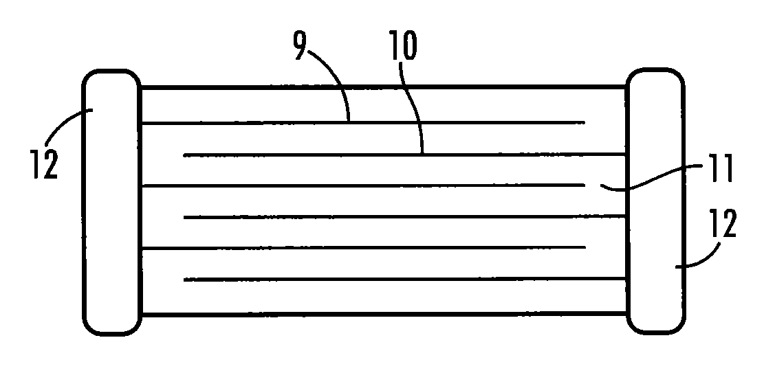
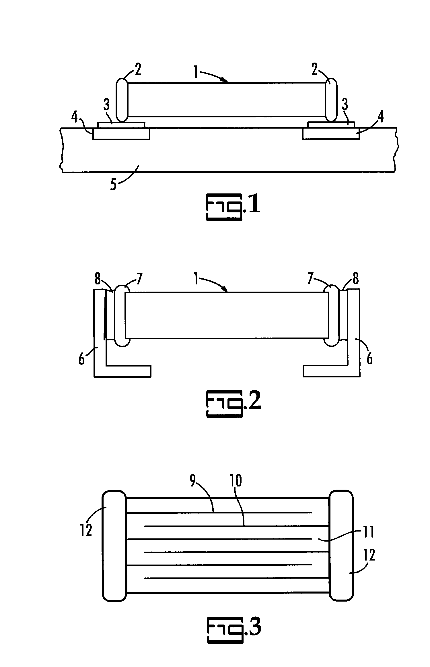
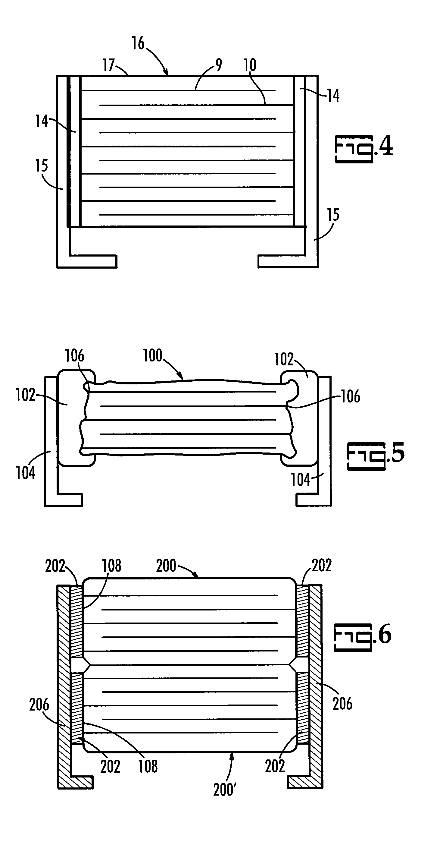
Image

Examples
example 1
Improved Mechanical Robustness of Polymer Solder
[0062]Sixty eight identical stacks each having 2 MLCC's with a case size of 0.22×0.20 inches mounted in a common lead frame were manufactured. The stacks were separated into two equal sets of 34 each. One set was a control set wherein the lead frame was attached to each MLCC using 1 mg of Sn / Sb solder with 91.5 wt % Sn and 8.5 wt % Sb. The second set was an inventive set wherein a lead frame was attached to each MLCC using 1 mg of Sn / Sb polymer solder with 91.5 wt % Sn and 8.5 wt % Sb available from Henkel as 10048-11A polymer solder. Each component was passed through a solder reflow oven at 260° C. three times and the part examined after each pass to determine the number of chips slumped. The results are provided in Table 1 wherein the cumulative number of failed parts is recorded after each pass.
TABLE 1Adhesive typePass #1Pass#2Pass#3Control456Inventive000
[0063]The results in Table 1 indicate that, for the control, 4 parts failed in ...
example 2
Improved Mechanical Robustness of TLPS
[0064]Similar stacks were manufactured with silver or tin plated lead frames and attached with a Cu-based transient liquid phase sintering adhesive available as Ormet 328. The samples did not exhibit any slumping or external lead detachment. A load test was then conducted as described in U.S. Pat. No. 6,704,189 wherein the stacks were placed in an oven with a 30 g weight attached to the MLCC and suspended below the stack. The temperature was increased above 260° C. in steps of at least 10° C. with a 10 minute dwell at each temperature. The parts were then examined for slumping and or external lead detachment failures. In the case of silver plated external lead frames failures were detected at 360° C. but for Sn plated lead frames the first failures were detected at 630° C. demonstrating a superior high temperature mechanical performance for transient liquid phase sintering conductive adhesive.
example 3
Temperature Capability of Polymer Solder
[0065]One hundred and twenty J-lead style stacks were manufactured using identical MLCC's, identical J-leads and thermo-compression bonding process. The samples were split into groups of 30 and each bonded using various volumes of 91.5 / 8.5 Sn / Sb solder, available as Henkel 92ADA100DAP85V EU 2460, for the control samples and polymer solder, available as Henkel 20048-11A, as the inventive samples containing the same solder composition. The samples were then sent through various soldering ovens over three passes and at different temperatures. The samples were then assessed for part slumping. The results are shown in FIG. 10. No slumping was detected in the polymer solder samples indicating improved high temperature robustness.
PUM
| Property | Measurement | Unit |
|---|---|---|
| Temperature | aaaaa | aaaaa |
| Temperature | aaaaa | aaaaa |
| Fraction | aaaaa | aaaaa |
Abstract
Description
Claims
Application Information