
Separation of gases produced by combustion

a technology of gaseous mixture and separation method, which is applied in the direction of separation process, liquefaction, lighting and heating apparatus, etc., can solve the problems of large equipment footprint, high energy consumption requirements, solvent/reactant loss during operation, and relatively ineffective methods and devices in separating gas components of gaseous mixtures

Inactive Publication Date: 2011-12-08
SHELL OIL CO
View PDF2 Cites 21 Cited by
  • Summary
  • Abstract
  • Description
  • Claims
  • Application Information

AI Technical Summary

Benefits of technology

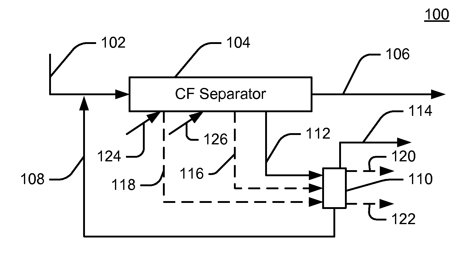
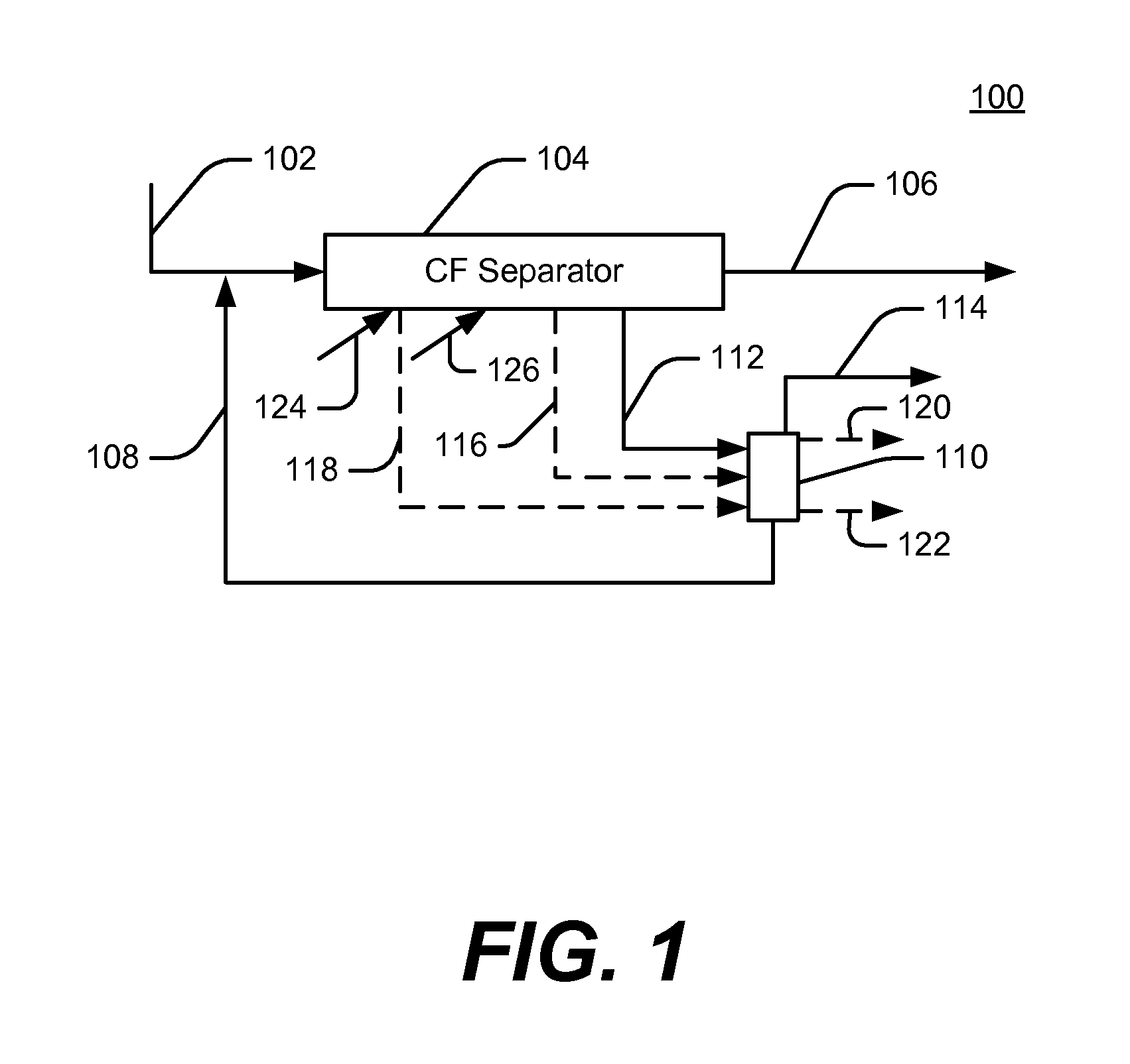
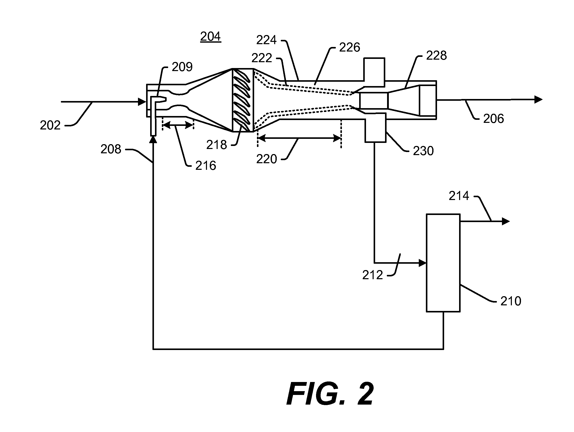
The present invention provides a method and system for separating a mixed stream of compressible and incompressible components derived from a combustion source. The method involves mixing the compressible feed stream with the incompressible fluid stream in a co-current flow and inducing a rotational velocity to the mixed stream. This results in the separation of an incompressible fluid product stream with a reduced amount of the compressible component and a compressible product stream with an increased amount of the compressible component. The system includes a separation device, an incompressible fluid regenerator, and an incompressible fluid injection device. The technical effects of the invention include improved separation efficiency and purity of the separated components.

Problems solved by technology

These methods and devices are relatively ineffective and / or inefficient in separating gas components of gaseous mixtures.
The equipment involved usually requires a large footprint due to the numerous pieces of process equipment needed for such a separation scheme.
Such a process may also suffer from high energy consumption requirements and solvent / reactant loss during operation.
When the gas stream contains too high of a target component concentration, the energy required to remove the target component may exceed the useful chemical energy of the stream.
This limitation sets an upper concentration level of the target component at which the process can be economically operated.
This process also suffers from a high energy consumption, solvent loss, and a large footprint, making the process impracticable for offshore use.
Thus, filters and membrane separations require a high energy consumption due to the energy required to re-compress the gas diffused through the membrane and, if the feed stream is at low pressure, the energy required to compress the feed stream to a pressure sufficient to diffuse one or more feed stream components through the membrane.
In addition, membrane life cycles can vary due to plugging and breakdown of the membrane, requiring additional downtime for replacement and repair.
The system involves a significant pressure drop between the inlet and outlet streams, and a shock wave occurs downstream after the separation, which may require specialized equipment to control.
As noted in the thesis, the potential to separate compressible components such as carbon dioxide from light hydrocarbons is limited by the differences in molecular weights between the components.
As such, centrifuges cannot provide a highly efficient separation when the component molecular weights are close to one another.
Such a design also suffers from an extremely low separation throughput rate that would require millions of centrifuges to handle the output of a large gas source.

Method used


Image

  • Separation of gases produced by combustion
  • Separation of gases produced by combustion
  • Separation of gases produced by combustion

Examples


specific embodiments

[0102]An embodiment of the process and device is schematically shown in FIG. 4. In this embodiment, the incompressible fluid regeneration device is a centrifugal separation device. In this embodiment, a compressible feed stream 402, which is a combustion gas stream that may be a flue gas stream for example, is first passed through a compressor 404 before being cooled in a heat exchanger 405. The compressible feed stream 402 may be compressed to a pressure ranging from 2 bar (0.2 MPa) to 200 bar (20 MPa). In an embodiment, the compressible feed stream 402 temperature is cooled to near the freezing point of the incompressible fluid selected to separate one or more compressible target components from the compressible feed stream to increase the solubility of the target component(s) in the incompressible fluid stream.

[0103]The compressed and cooled compressible feed stream 408 is fed into the separation device 414. The compressed, cooled compressible feed stream 408 is combined with an ...


PUM

PropertyMeasurementUnit
temperatureaaaaaaaaaa
pressureaaaaaaaaaa
exhaust temperatureaaaaaaaaaa

Abstract

The present invention is directed to a method and a system for separating gas components of a combustion gas. A compressible feed stream derived from a combustion gas that contains at least one target compressible component and at least one non-target compressible component is mixed in a substantially co-current flow with an incompressible fluid stream comprising an incompressible fluid in which the target component(s) is / are capable of being preferentially absorbed. Rotational velocity is imparted to the mixed streams, separating an incompressible fluid in which at least a portion of the target component is absorbed from a compressible product stream containing the non-target compressible component(s). The compressible feed stream may be provided at a stream velocity having a Mach number of at least 0.1.

Description

FIELD OF THE INVENTION[0001]The invention relates to the separation of one or more components from a fluid stream containing a plurality of components. More particularly, the invention relates to a system and method for removing one or more compressible components from a compressible flue gas stream using a separation device and an incompressible fluid.BACKGROUND OF THE INVENTION[0002]Numerous methods and apparatus exist for separating components from a fluid stream containing gases, liquids and / or solids. Conventional separation apparatuses include distillation columns, stripping columns, filters and membranes, centrifuges, electrostatic precipitators, dryers, chillers, cyclones, vortex tube separators, and absorbers. These methods and devices are relatively ineffective and / or inefficient in separating gas components of gaseous mixtures.[0003]For example, a commonly utilized system and method for separation of hydrogen sulfide (H2S) or carbon dioxide (CO2) from a gas stream involve...

Claims


Application Information

Patent Timeline
Patent Type & Authority Applications(United States)
IPC IPC(8): B01D53/24F25J3/08B01D53/14
CPCB01D45/12B01D53/1425B01D53/1456B01D53/18B01D53/79F23J15/04B01D2257/504B01D2259/124F23J15/006F23J15/02B01D2257/302Y02E20/32
Inventor BUHRMAN, FREDERIK ARNOLDCUI, JINGYUJOSHI, MAHENDRA LADHARAMMILAM, STANLEY NEMECWELLINGTON, SCOTT LEE
Owner SHELL OIL CO
Learn More