RF power amplifier circuit with mismatch tolerance

a power amplifier and mismatch tolerance technology, applied in the direction of amplification control details, high frequency amplifiers, gain control, etc., can solve the problems of sacrificing more power efficiency, affecting the efficiency of pa, and undesirable wide spectral occupancy, etc., to achieve the effect of improving pa efficiency

Active Publication Date: 2011-12-08
QUANTANCE
View PDF3 Cites 101 Cited by
  • Summary
  • Abstract
  • Description
  • Claims
  • Application Information

AI Technical Summary

Benefits of technology

[0013]Embodiments of the present invention include a radio frequency (RF) power amplifier system that adjusts the supply voltage provided to the PA adaptively, responsive to the measured or estimated power of the RF output signal of the PA. The RF PA system includes a power amplifier (PA) which receives and amplifies an RF input signal to generate an RF output signal at a level suitable for transmission to an antenna. A PA VCC (supply voltage)

Problems solved by technology

RF PAs are one of the most significant sources of power consumption in these electronic devices, and their efficiency has a significant impact on the battery life of these portable electronic devices.
Since the RF spectrum is shared amongst users of the cellular telephone, a wide spectral occupancy is undesirable.
This typically results in power being wasted during the off-peak of the amplitude of the RF input signal 106, as the biasing remains fixed for the acceptable distortion at the peak power level.
Certain RF modulation techniques have evolved to require even more spectral efficiency, and thereby forcing the PA 104 to sacrifice more power efficiency.
However, the supply voltage 108 cannot be reduced too low, because this would cause the PA 104 to operate with insufficient voltage headroom, resulting in unacceptable distortion.
As described previously, the distortion may cause energy from the transmitted signal to spill over to adjacent channels, increasing spectral occupancy and causing interference to radios operating in those neighboring channels.
However, choosing a fixed power supply voltage is

Method used


Image

  • RF power amplifier circuit with mismatch tolerance
  • RF power amplifier circuit with mismatch tolerance
  • RF power amplifier circuit with mismatch tolerance

Examples


first embodiment

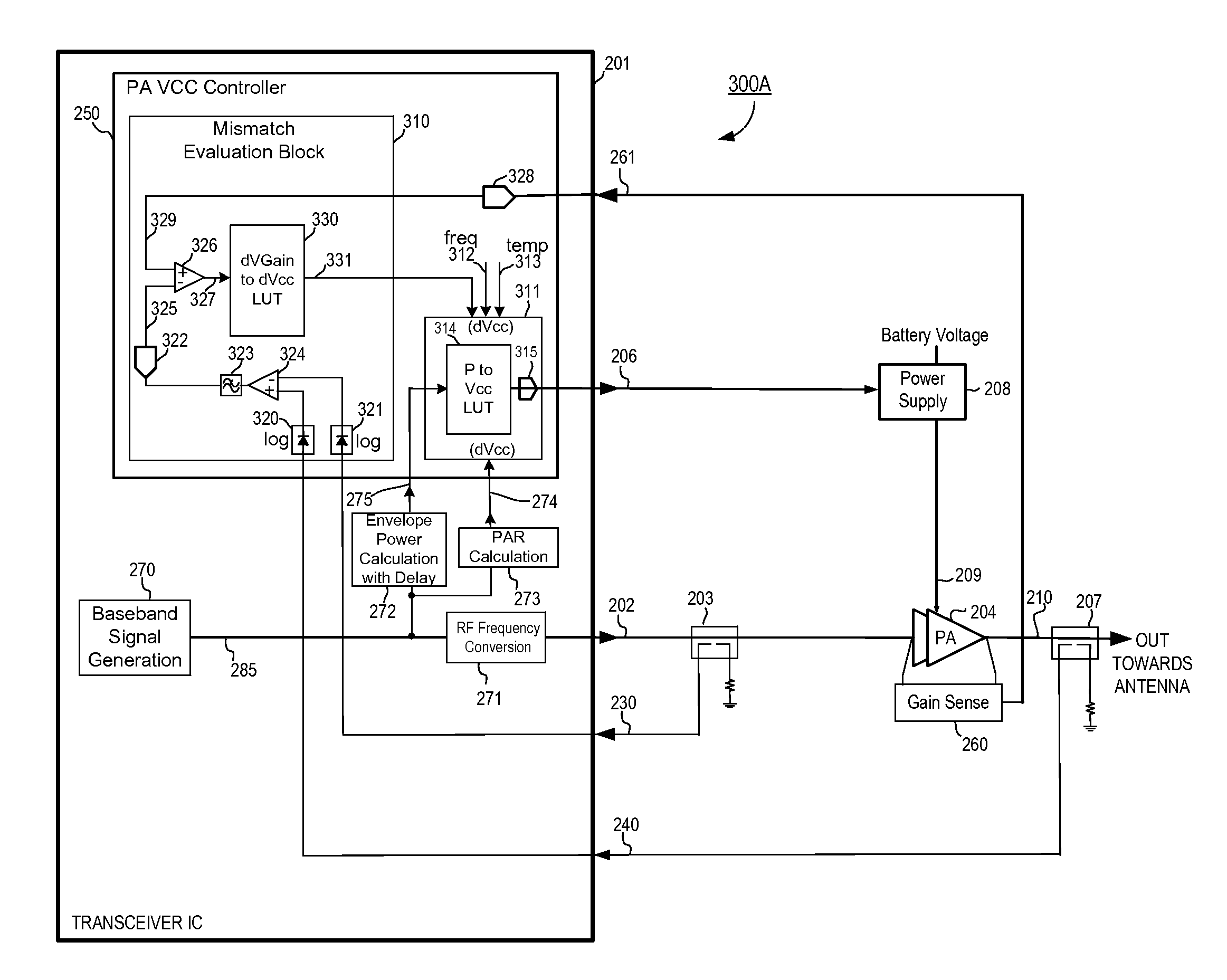
[0041]FIG. 3A illustrates an RF PA system 300A that includes the details of the PA VCC controller according to the present invention. Specifically, FIG. 3A illustrates the operation of mismatch evaluation block 310, the generation of mismatch indicator signal 331, and the Vcc control block 311 in more detail. “Mismatch” in this context refers to the impedance mismatch seen at the output 210 of PA204. The antenna circuitry following PA 204 typically has nominal impedance around the range of 50 ohms. However, the impedance of the antenna circuitry can sometimes change radically from the nominal impedance. For example, if the antenna is touched or the cellular device is laid down on a metal surface, the impedance of the antenna changes, reflecting impedance changes back to the output 210 of PA 204. The changes in the impedance of the antenna circuitry coupled to the output 210 of the PA 204 may necessitate changes in the VCC supply voltage 209 to the PA 204 to prevent distortion of the...

second embodiment

[0046]FIG. 3B illustrates an RF PA system that includes the details of the PA VCC controller according to the present invention. The RF PA system 300B of FIG. 3B is a variation to the RF PA System 300A shown in FIG. 3A. In this case, VCC control block 310 is configured to respond directly to the measured power envelope of the output signal 210 of PA 204 through forward sampled power signal 240 from directional coupler 207, as indicated by envelope detector 2720, rather than responding to an estimate of the power envelope of output signal 210 utilizing the calculations made with envelope power calculation block 272, as described earlier with reference to FIG. 3A. In this example, envelope detector 2720 tracks the instantaneous power envelope of the RF output signal 210 of PA 204. Thus, the VCC control block 3110 is comprised of predominantly analog components, in order to speed the response of PA VCC voltage 209, since the power envelope of the output signal 210 must track with the P...

third embodiment

[0049]FIG. 3C illustrates an RF PA system that includes the details of the PA VCC controller according to the present invention. The RF PA system 300C of FIG. 3C is also a variation of the RF PA system 300A of FIG. 3A. In the RF PA system 300C of FIG. 3C, mismatch evaluation block 310 evaluates the degree of impedance mismatch as seen at the output 210 of PA 204 by calculating the difference or ratio between the nominal power gain of PA 204—as expected with PA 204 driving nominal impedance at its output 210 with no mismatch—and the actual measured gain of PA 204, and generates mismatch indicator signal 351 to indicate whether PA VCC voltage 209 should be increased or decreased due to this impedance mismatch at the output 210 of PA 204. Mismatch indicator signal 351 is then input to VCC control block 311, influencing PA VCC controller 250 for generating a VCC control signal 206, which in turn controls the output voltage 209 from power supply 208 which feeds PA 204. In some cases, the...


PUM


Abstract

A radio frequency (RF) power amplifier system adjusts the supply voltage provided to a power amplifier (PA) adaptively, responsive to the measured or estimated power of the RF output signal of the PA. The RF PA system includes a power amplifier (PA) which receives and amplifies an RF input signal to generate an RF output signal at a level suitable for transmission to an antenna. A PA supply voltage controller generates a supply voltage control signal, which is used to control the supply voltage to the final stage of the PA. The supply voltage control signal is generated responsive to the measured or estimated power of the PA RF output signal, and also may be responsive to a parameter indicative of impedance mismatch experienced at the PA output. By controlling this supply voltage to the RF PA, the efficiency of the PA is improved.

Description

BACKGROUND[0001]1. Field of the Invention[0002]The present invention relates to a circuit for controlling RF PAs (Radio Frequency Power Amplifiers), and more specifically, to an RF PA controller circuit that adjusts the supply voltage of RF PAs.[0003]2. Description of the Related Art[0004]RF (Radio Frequency) transmitters and RF power amplifiers are widely used in portable electronic devices such as cellular phones, laptop computers, and other electronic devices. RF transmitters and RF power amplifiers are used in these devices to amplify and transmit the RF signals remotely. RF PAs are one of the most significant sources of power consumption in these electronic devices, and their efficiency has a significant impact on the battery life of these portable electronic devices. For example, cellular telephone makers make great efforts to increase the efficiency of the RF PA systems, because the efficiency of the RF PAs is one of the most critical factors determining the battery life of t...

Claims


Application Information

Patent Timeline
IPC IPC(8): H03G1/00H03G3/20
CPCH03F1/0227H03F1/0211H03F1/3247H03F1/56H03F3/189H03F3/195H03F3/245H03F2200/102H03F2200/105H03F2200/192H03F2200/195H03F2200/204H03F2200/207H03F2200/375H03F2200/387H03F2200/411H03F2200/435H03F2200/465H03F2200/504H03F2200/78H03G3/3042H03F1/302H03F3/04
Inventor DROGI, SERGE FRANCOISTOMASZ, MARTIN
Owner QUANTANCE
Why Eureka
Try Eureka