Digital phase comparator

a digital phase comparator and comparator technology, applied in the field of phase comparator, can solve the problems of deterioration of characteristics, voltage reduction, and inability to gain such benefits as size reduction or cost reduction, and achieve the effect of reducing circuit area and power consumption

Active Publication Date: 2011-12-15
NEC CORP
View PDF4 Cites 29 Cited by
  • Summary
  • Abstract
  • Description
  • Claims
  • Application Information

AI Technical Summary

Benefits of technology

[0011]This invention uses two different phase difference signals, namely first phase difference signals and second phase difference signals. The first phase difference signals are phase difference signals obtained by sampling a second clock signal using a first group of clock signals which are equally spaced. The second phase difference signals are generated based on a first clock signal and a first signal obtained by performing a logic operation on the first phase difference signals. The first phase difference signals cover a cycle period of the second clock signal. The second phase difference signals cover a resolution of the first phase difference signals, which makes it possible to reduce the circuit area and power consumption. The use of these two different phase difference signals makes it possible to provide a high-resolution digital phase comparator without causing increase in circuit area or power consumption.

Problems solved by technology

Such an analog PLL cannot gain such benefits as size reduction or cost reduction as a result of miniaturization of the circuit because it uses elements such as resistances and capacitances in its loop filter or the like.
Moreover, the voltage is lowered by the miniaturization, which poses a problem of deterioration in characteristics due to source noise or the like.

Method used


Image

  • Digital phase comparator
  • Digital phase comparator
  • Digital phase comparator

Examples


first exemplary embodiment

[0037]A first exemplary embodiment of this invention will be described in detail with reference to the drawings. FIG. 5 shows an overall configuration of a PLL circuit comprising a digital phase comparator according to the invention, and then FIG. 6 shows a block diagram of a configuration of a digital phase comparator according to a first exemplary embodiment of the invention.

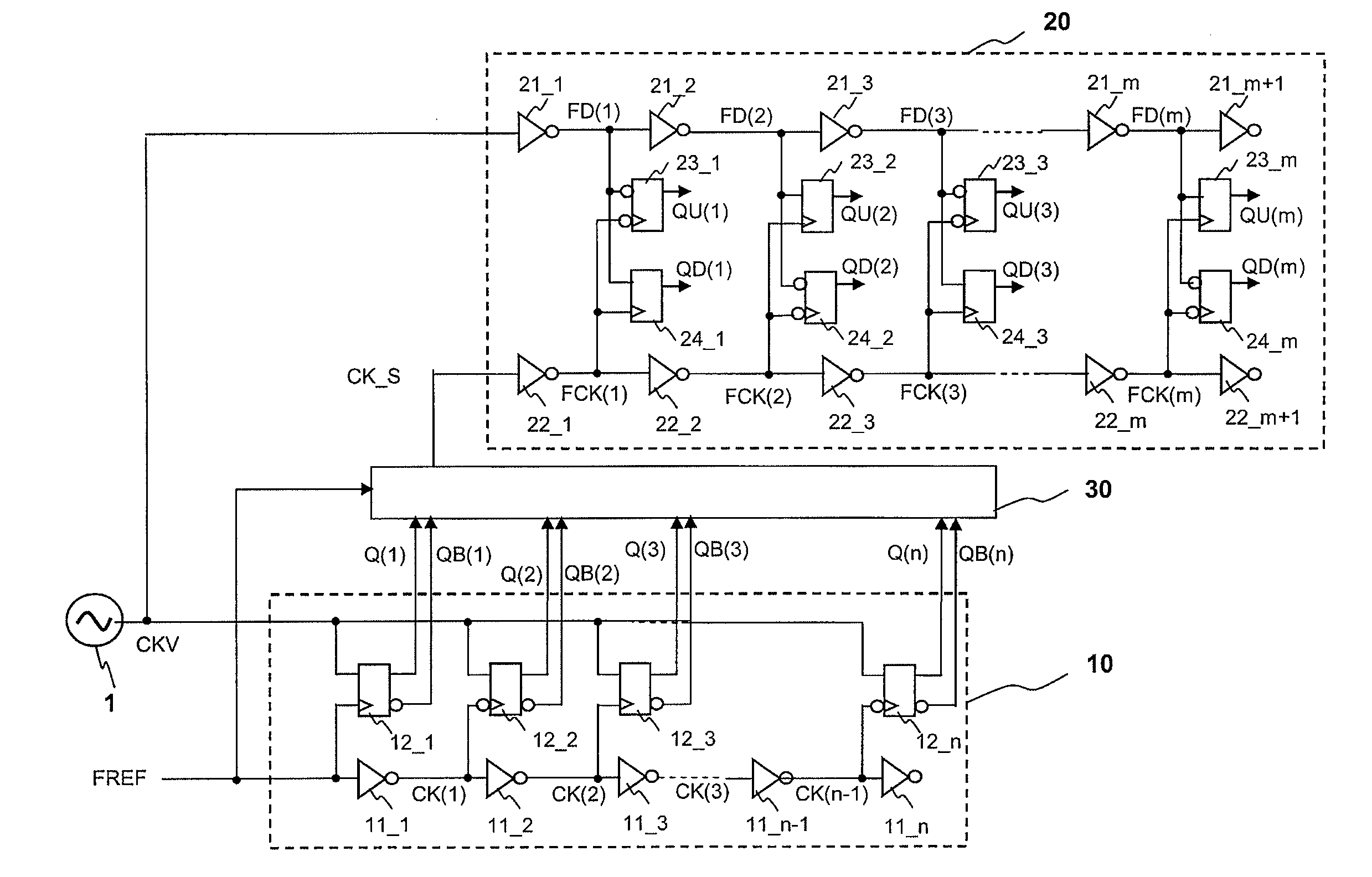
[0038]The digital PLL circuit of this invention shown in FIG. 5 comprises a VCO (voltage-controlled oscillator) 1, a time-digital converter 10, a timing extractor 30, a time-digital converter 20, and a logic circuit 2. The time-digital converter 10, the timing extractor 30, and the time-digital converter 20 are collectively referred to as a digital phase comparator. Here, the description of this invention will be made in terms of detection of a phase difference of one cycle or less of the VCO and correction thereof. An output signal CKV from the VCO is supplied to the time-digital converter 10, the time-digita...

example 1

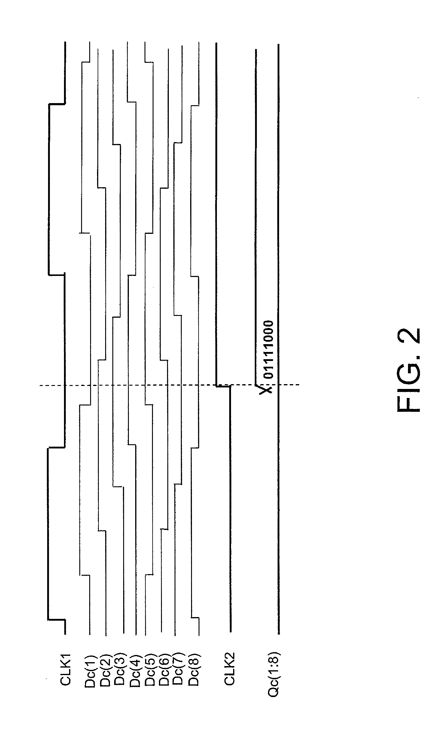
[0052]A specific example relating to this exemplary embodiment of the invention will be described in detail with reference to the drawings. FIGS. 8 to 10 are timing charts when n=8 and m=4 in the first exemplary embodiment shown in FIGS. 6 and 7. FIG. 8 is a timing chart relating to the time-digital converter 10, FIG. 9 is a timing chart relating to the timing extractor 30 when n=8 in FIG. 7, and FIG. 10 is a timing chart relating to the time-digital converter 20 when m=4 in FIG. 6.

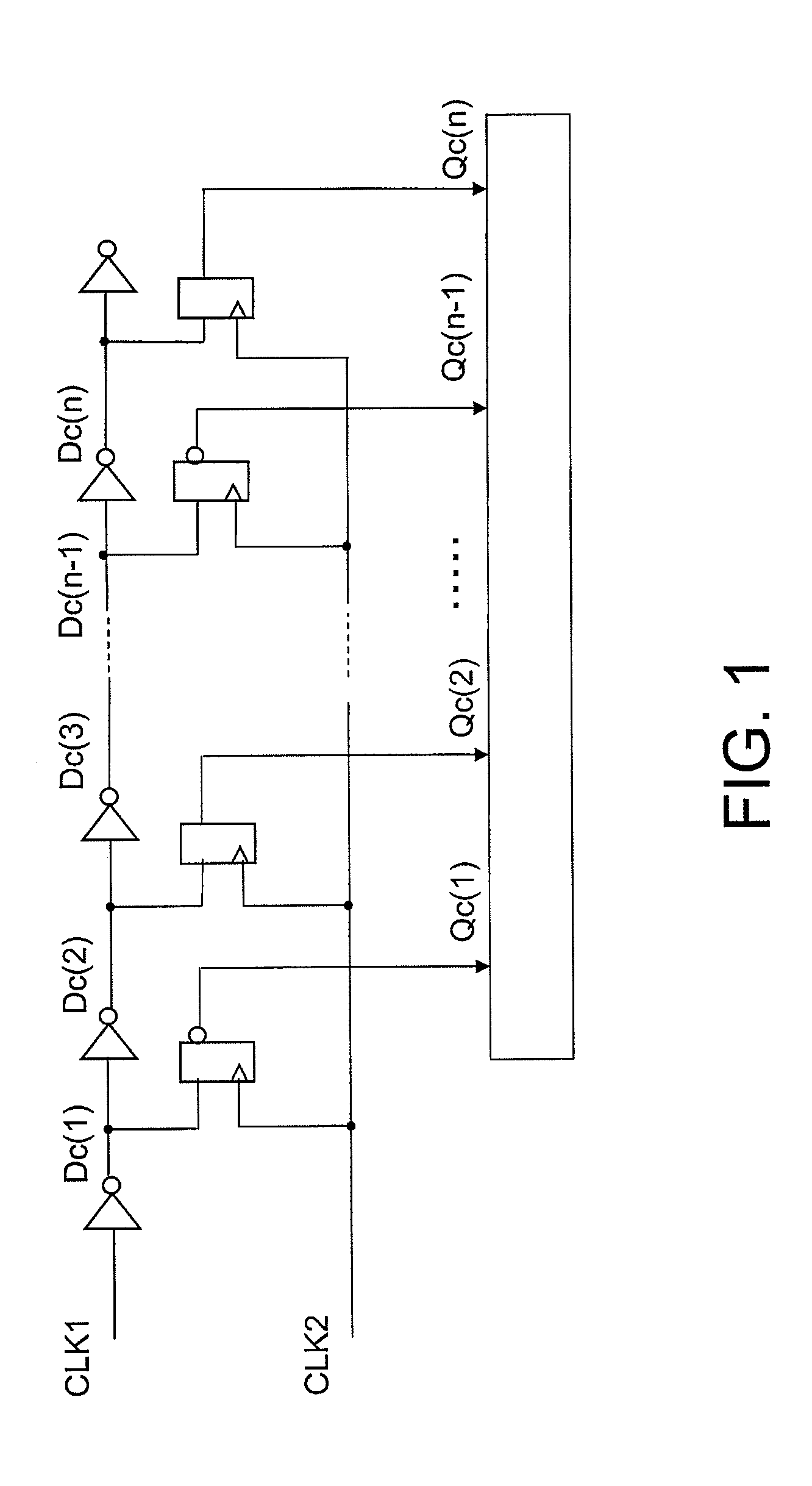
[0053]FIG. 8 is the timing chart relating to the time-digital converter 10. With respect to the rising edge of the reference clock signal FREF, a phase difference at the rising of the VCO output signal CKV is denoted by Tr, a phase difference at the falling edge thereof is denoted by Tf. The time-digital converter 10 in the digital phase comparator of this example has the same configuration as the time-digital converter 10 comprising the inverter array 11_1 to 11_8, and the flip-flops 12_1 to 12_8 as show...

second exemplary embodiment

[0070]FIG. 11 is a block diagram illustrating a digital phase comparator according to a second exemplary embodiment of this invention. Referring to FIG. 11, the digital phase comparator has a configuration in which a timing adjuster 40 is additionally provided between the VCO and the second time-digital converter 20 in the first embodiment shown in FIG. 6.

[0071]FIG. 12 is a block diagram illustrating a configuration of the timing adjuster 40 according to the second exemplary embodiment shown in FIG. 11. Referring to FIG. 12, the timing adjuster 40 comprises flip-flops 41_1, 41_2, composite logic gates 42_1, 42_2, OR gates 43, 44, reset-set flip-flops 45, 46, exclusive OR gates 47, 48, and a selector 49. The flip-flops 41_1, 41_2 are set so as to have the same delay time as that of the flip-flops 12_1 to 12—n in the time-digital converter 10.

[0072]The composite logic gates 42_1, 42_2, the OR gates 43, 44, the reset-set flip-flops 45, 46, the exclusive OR gates 47, 48, and the selecto...


PUM


Abstract

A digital phase comparator is provided in which first phase difference signals and second phase difference signals are used as digital phase difference information. The first phase difference signals are generated by sampling a second clock signal with a first group of clock signals having regular intervals. The second phase difference signals are generated, using a second group of clock signals and a first group of signals which are obtained by delaying a second clock signal and a first signal generated by performing a logic operation on the first phase difference signal respectively at different regular intervals, by sampling the second group of clock signals with the first group of signals.

Description

TECHNICAL FIELD[0001]This invention relates to a phase comparator, in particular to a digital phase comparator for detecting a phase difference to convert it to a digital signal.BACKGROUND ART[0002]Recently, in the field of LSIs (Large Scale Integrated circuits) for wireless communication to which a fine CMOS (Complementary MOS (Metal-Oxide-Semiconductor)) process is applied, the degree of integration has been increased. In conventional LSIs for wireless communication, an analog PLL circuit is usually employed as a PLL (Phase Locked Loop) circuit.[0003]In the case of an analog PLL circuit, phase difference information is produced by a phase comparator (PD) as a pulse width, and electrical charge that is produced by a charging pump circuit (CP) according to the pulse width is converted into voltage information by a loop filter. Oscillating frequency is controlled by supplying the voltage information from the loop filter into a control voltage terminal of a VCO (Voltage Controlled Osc...

Claims


Application Information

Patent Timeline
Patent Type & Authority Applications(United States)
IPC IPC(8): H03D13/00
CPCH03K5/26H03D13/006H03L2207/50H03L7/091
Inventor TOKAIRIN, TAKASHI
Owner NEC CORP
Why Eureka
Try Eureka