
Apparatus and methods for radiation treatment of tissue surfaces

a tissue surface and apparatus technology, applied in the field of tissue surface radiation therapy, can solve the problems of limited conformity, external beam sources, limited radiation dose uniformity, etc., and achieve the effects of increasing treatment efficiency, reducing radiation dose, and increasing spacing

Active Publication Date: 2011-12-15
XOFT INC
View PDF0 Cites 1 Cited by
  • Summary
  • Abstract
  • Description
  • Claims
  • Application Information

AI Technical Summary

Benefits of technology

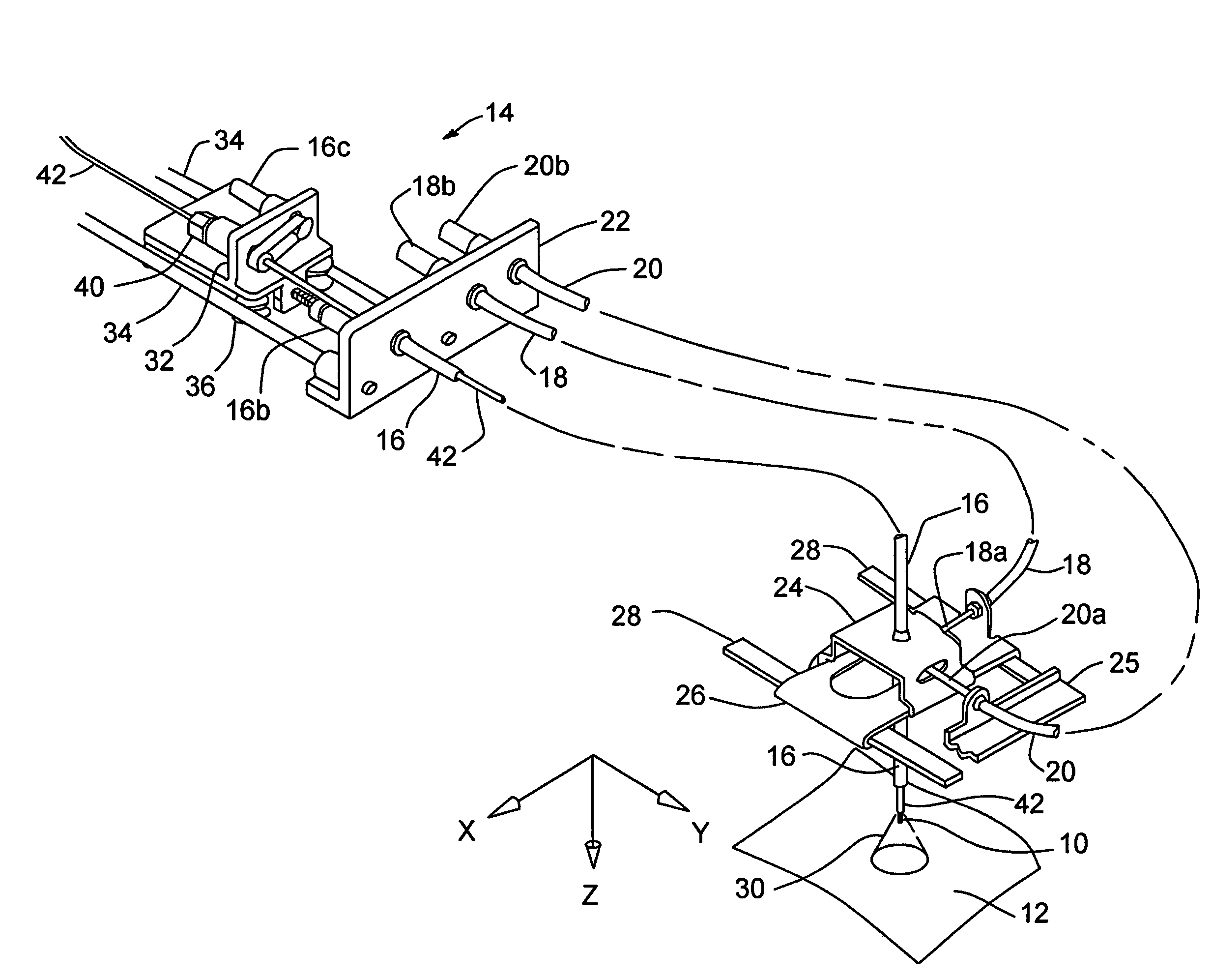
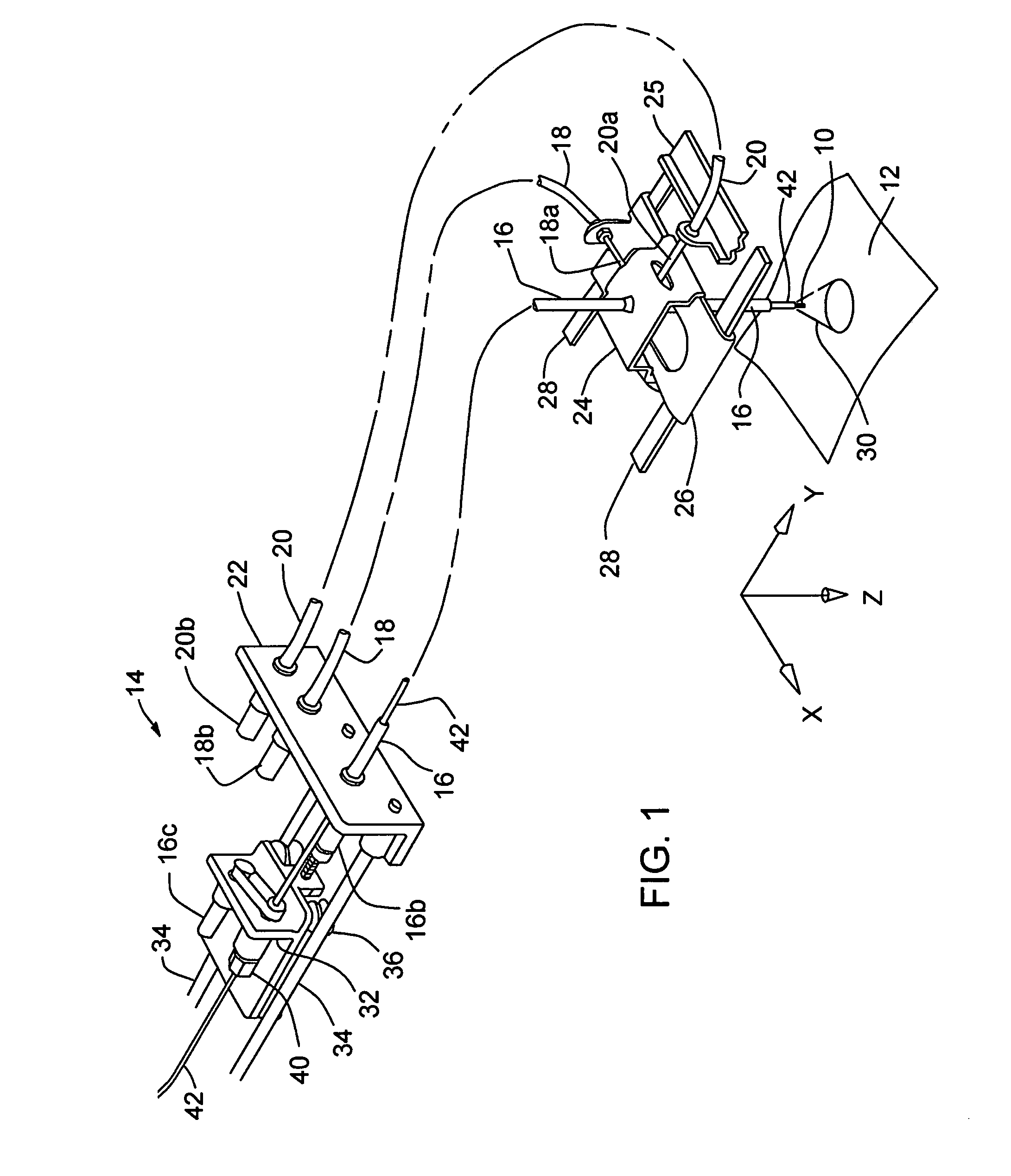
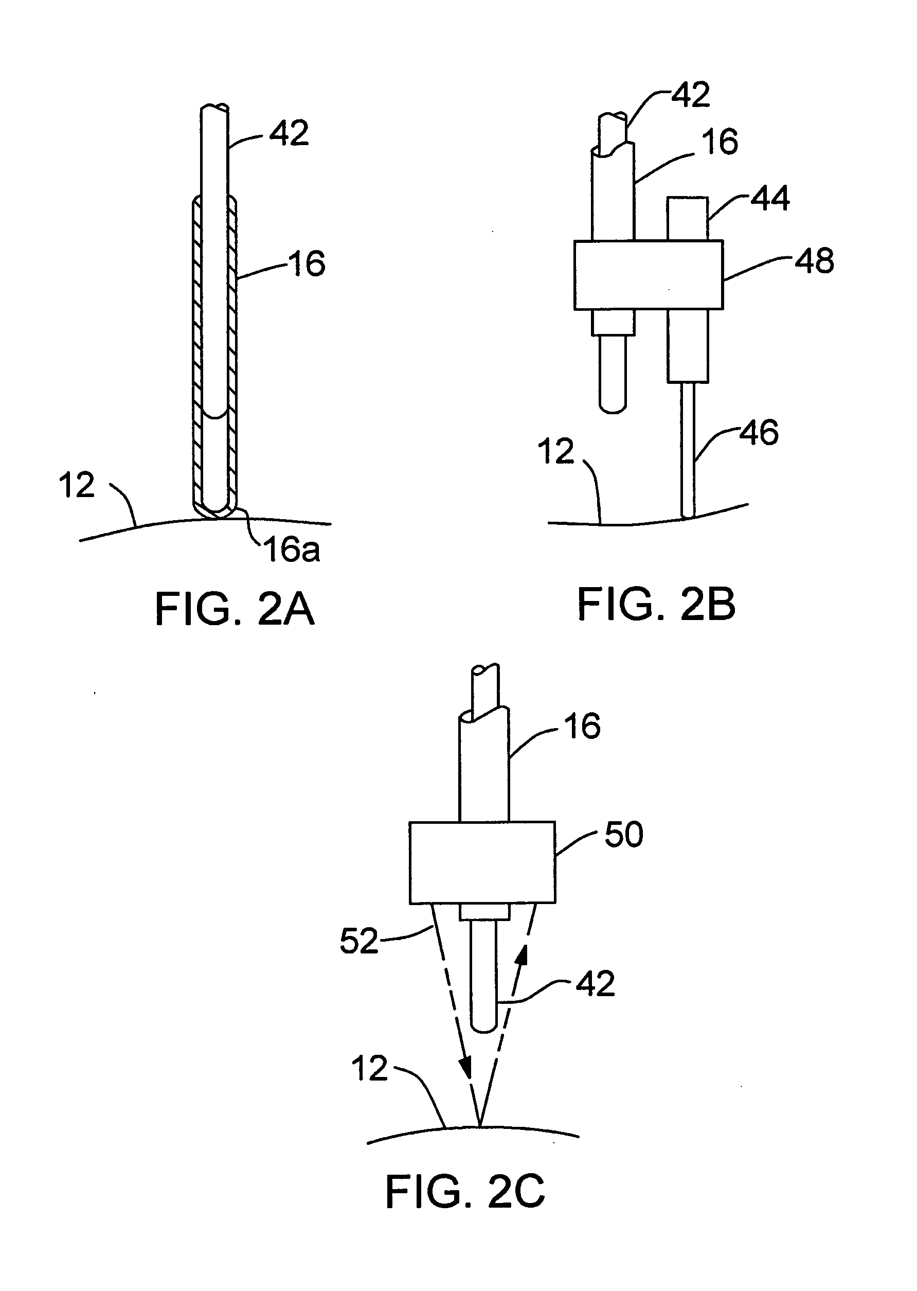
[0017]A preferred contact style probe is a catheter sheath with a preferably substantially spherical contact surface of about one (1) cm radius, with the source at the center of the spherical portion. The spherical portion glides on a fairly rigid surface overlying the target tissue to maintain Z control, hence proper range. We have discovered that an advantage of such an embodiment over prior art teaching is an unexpected increase in treatment efficiency. Where the generally spherical portion of the catheter or applicator terminus meets the contact surface, there is, in principle, only point contact so long as any surface undulations are not severe. The air gap formed around the point of contact does not significantly attenuate the radiation intensity lateral of the contact point. Prior art methods of surface treatment teach substantial, intimate contact with the target tissue rather than creating an air gap, and limitation of the direction of radiation to an area toward which the applicator is directed. Hence with this invention, the absorbed dose laterally of each contact point provides a greater contribution to the cumulative dose at each such point, thereby allowing greater spacing between dwell points, and hence faster treatment times for any target area. We have even found this increase to be sufficient to still provide a substantial improvement in absorbed dose even when the contact surface is comprised of a material which attenuates the lateral radiation. A preferred example of such a contact sheet is aluminum which also provides radiation hardening—a further advantage. A variation on this embodiment is a source catheter tip of radiation hardening nature, and a more radiation-transparent contact surface, or no overlying contact surface, where the source guide glides on or just above the target tissue.
[0018]The spherical end component preferably comprises a solid material surrounding the source, with selected attenuating (or beam hardening) characteristics. The spherical shape assures uniform attenuation in all directions, assisting in treatment planning. It also provides the option to distribute the radiation non-symmetrically in a desired way. In one direction beam attenuation or full shielding could be provided, and in other directions, for example, less attenuation or beam hardening could be provided.
[0020]Another advantage with this invention is that, where target surfaces are not severely undulating and where Z control is responsive to the surface or can be preprogrammed as a function of X,Y positioning, many three dimensional cases can be managed by two dimensional (X,Y) rastering methods, providing a great advantage in the planning process and in time required in the operating room.

Problems solved by technology

Their source guides have fixed spacing which may or may not be conducive to an optimal treatment plan, and further, the discrete spacing of the source guides within the applicator may contribute to non-uniformity in the delivered radiation dose.
Still further, the applicator may have structural characteristics limiting its ability to conform adequately to the surface being treated without interfering with ease of source manipulation within the source guides.
They also emit continuously, and thus, like external-beam sources, can only be used in special, heavily-shielded rooms.
This can result in under-serving rural patients who cannot repeatedly travel to urban treatment centers for a course of prolonged radiation treatment.
Furthermore, the need for patient isolation is inconvenient for therapists, not to mention daunting for patients under treatment.
Radionuclides cannot be controlled in this manner as easily.

Method used


Image

  • Apparatus and methods for radiation treatment of tissue surfaces
  • Apparatus and methods for radiation treatment of tissue surfaces
  • Apparatus and methods for radiation treatment of tissue surfaces

Examples


Embodiment Construction

[0030]Each case where radiotherapy of a surface area is indicated first involves planning. The area to be treated needs to be identified, and a prescription specified by a radiation oncologist. The prescription may involve local dose variations depending on the uniformity of the disease, its progression or extent as presented.

[0031]Planning also requires characterization of the source to be used, measured so as to include any attenuating effects from collateral apparatus which will be positioned within the emission pattern during the treatment to be performed. This characterization information is fed into the planning program for use in development of the treatment plan which in turn will later be used in establishing apparatus control parameters for the therapy.

[0032]With a prescription established and the source properly characterized and with both input into the treatment planning system, determination of a rastering treatment protocol, including proper control of apparatus param...


PUM


Abstract

A device, system and method for administering radiation therapy to a tissue surface of a patient utilizes an applicator capable of controlled movement and repositioning over a selected area of tissue, under the control of a computer or controller. A servo-controlled manipulator can effect a raster scan of the desired area, such as an area of the skin, and this can be in any desired pattern such as serpentine, spiral, parallel but unidirectional, or irregular patterns. Preferably a third direction of control is included, i.e. a depth direction, with an appropriate form of depth sensor, a signal from which can be used to adjust the radiation source so that radiation of the tissue surface is consistent over varied contoured.

Description

BACKGROUND OF THE INVENTION[0001]This invention relates to radiation therapy of tissue surfaces as adjuvant or primary care for proliferative disease or other pathological conditions or as primary treatment. Discussion herein is largely directed to radiotherapy of exposed anatomical surfaces, e.g. skin, for treatment of proliferative disease, but it is to be understood that the apparatus and methods may be applied to different anatomical sites whether naturally occurring or as a result of surgical intervention, and for other therapeutic purposes.[0002]It has been demonstrated in many areas of surgical oncology that adjuvant radiation treatment following tumor resection reduces the likelihood of recurrence of cancer or other proliferative disease. The likelihood of infiltrative disease decreases with distance from a primary site in a tissue with confirmed disease.[0003]Commonly used traditional methods of radiation surface treatment would include positioning low energy radionuclide s...

Claims


Application Information

Patent Timeline
Patent Type & Authority Applications(United States)
IPC IPC(8): A61N5/10A61N5/00
CPCA61N5/00A61N5/103A61N5/10A61N5/1043A61N2005/1091
Inventor HOLT, RANDALL W.AXELROD, STEVEBURNSIDE, ROBERTNEIMEYER, ROBERT G.RUSCH, THOMAS W.
Owner XOFT INC
Learn More