Manufacturing method of power storage device

a power storage device and manufacturing method technology, applied in the manufacture of electrodes, cell components, electrolytic capacitors, etc., can solve the problems of reducing deterioration expansion of the volume of silicon, so as to improve the cycle characteristics and the like increase the surface area of the active material, and improve the performance of the power storage device.

Inactive Publication Date: 2012-01-05
SEMICON ENERGY LAB CO LTD
View PDF6 Cites 18 Cited by
  • Summary
  • Abstract
  • Description
  • Claims
  • Application Information

AI Technical Summary

Benefits of technology

[0019]According to one embodiment of the present invention, a surface area of an active material is increased by including a whisker; thus, various performances of a power storage device, for example, the charge and discharge capacities can be improved.
[0020]Moreover, cycle characteristics and the like of a power storage device can be improved by including a crystalline semiconductor layer which is

Problems solved by technology

However, there has been a problem in that the volume of silicon expands when the reactive material is occluded and released.
Thus, separation (also referred to as peeling) of silicon from the el

Method used


Image

  • Manufacturing method of power storage device
  • Manufacturing method of power storage device
  • Manufacturing method of power storage device

Examples


embodiment 1

[0033]In this embodiment, a manufacturing method, a structure, and performance of a power storage device will be described.

[0034]FIGS. 1A to 1C illustrate a manufacturing method of an electrode of a power storage device.

[0035]First, a current collector 101 is prepared (FIG. 1A). The current collector 101 functions as a terminal which extracts electricity.

[0036]The current collector 101 can be formed using a metal material typified by platinum, aluminum, copper, or titanium. The current collector 101 may be formed using an aluminum alloy to which an element which improves heat resistance, such as silicon, titanium, neodymium, scandium, or molybdenum, is added. Note that the current collector 101 can have a foil shape, a plate shape, a net shape, or the like.

[0037]Next, surface treatment is performed on the current collector 101 (FIG. 1B). For example, treatment with a hydrofluoric acid whose concentration is higher than or equal to 0.1% and lower than or equal to 1% is performed for ...

embodiment 2

[0070]In this embodiment, a specific example of the structure of the power storage device will be shown.

[0071]FIG. 3A is an enlarged view of a region surrounded with a dashed line 105 in FIG. 1C.

[0072]As illustrated in FIG. 3A, the crystalline semiconductor layer 103 (the active material layer) includes a crystalline semiconductor region 103a which covers the current collector 101 and a crystalline semiconductor region 103b including a whisker (the protrusion 103c), which is formed over the crystalline semiconductor region 103a. That is, the crystalline semiconductor layer 103 includes a whisker.

[0073]Note that the interface between the crystalline semiconductor region 103a and the crystalline semiconductor region 103b is not clear. Therefore, a plane that is at the same level as the bottom of the deepest valley among valleys formed between the protrusions 103c and is parallel to a surface of the current collector 101 is regarded as the interface between the crystalline semiconducto...

embodiment 3

[0091]In this embodiment, a structure of a power storage device will be described with reference to FIGS. 4A and 4B.

[0092]First, a structure of a secondary battery is described below as a power storage device.

[0093]Among secondary batteries, a lithium ion battery formed using a metal oxide containing lithium, such as LiCoO2, has a large discharge capacity and high safety. Here, a structure of a lithium ion battery, which is a typical example of the secondary battery, will be described.

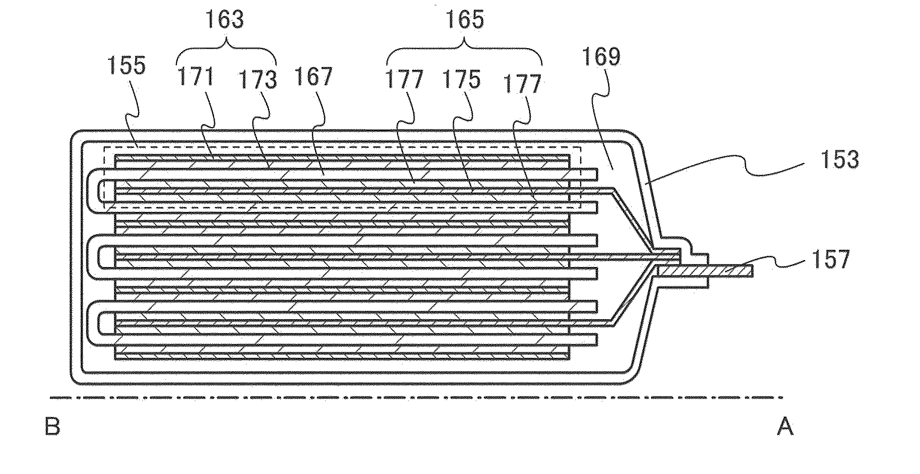
[0094]FIG. 4A is a plan view of a power storage device 151, and FIG. 4B is a cross-sectional view taken along dot-dashed line A-B in FIG. 4A.

[0095]The power storage device 151 in FIG. 4A includes a power storage cell 155 in an exterior member 153. The power storage device 151 further includes a terminal portion 157 and a terminal portion 159 which are connected to the power storage cell 155. For the exterior member 153, a laminate film, a polymer film, a metal film, a metal case, a plastic case, or the...


PUM


Abstract

It is an object to improve performance of a power storage device, such as cycle characteristics. A power storage device includes a current collector and a crystalline semiconductor layer including a whisker, which is formed on and in close contact with the current collector. Separation of the crystalline semiconductor layer is suppressed by an increase of adhesion, whereby cycle characteristics in which a specific capacity of a tenth cycle number with respect to a first cycle number is greater than or equal to 90% is realized. In addition, cycle characteristics in which a specific capacity of a hundredth cycle number with respect to a first cycle number is greater than or equal to 70% is realized.

Description

TECHNICAL FIELD[0001]The technical field of the present invention relates to a power storage device and a method for manufacturing the power storage device.[0002]Note that the power storage device indicates all elements and devices which have a function of storing power.BACKGROUND ART[0003]In recent years, power storage devices such as lithium-ion secondary batteries, lithium-ion capacitors, and air cells have been developed.[0004]As an active material of an electrode for the power storage device, for example, a material such as carbon or silicon is used. In the power storage device, these materials can occlude and release a reactive material (e.g., lithium ions). In addition, silicon (or phosphorus-doped silicon) has an advantage of larger theoretical capacity than carbon and larger capacity of a power storage device (e.g., Patent Document 1).REFERENCE [0005][Patent Document 1] Japanese Published Patent Application No. 2001-210315DISCLOSURE OF INVENTION[0006]However, there has bee...

Claims


Application Information

Patent Timeline
IPC IPC(8): H01M4/02H01L21/02H01M4/13H01G9/15H01M4/134H01M4/1395H01M4/38H01M4/64H01M4/66H01M10/052
CPCH01G11/06H01G11/12H01G11/28H01G11/70H01G11/86H01L28/84Y02E60/13H01M4/134H01M4/1395H01M4/667H01M10/052Y02E60/122H01M4/0428Y02E60/10
Inventor KURIKI, KAZUTAKAKONISHI, MICHIKOTADOKORO, ASAMIYOSHIDA, YASUNORIOGINO, KIYOFUMITAKEUCHI, TOSHIHIKO
Owner SEMICON ENERGY LAB CO LTD
Why Eureka
Try Eureka