Apparatus and method for deposition of functional coatings

a functional coating and apparatus technology, applied in chemical vapor deposition coatings, flexible pipes, railway signalling, etc., can solve the problems of complex chemistry that cannot be deposited using such systems, cannot contain enough energy to fragment all of the bonds within a monomer, and the functionality of the coating remains limited to simple materials. , to achieve the effect of reducing maintenance requirements, simplifying equipment design, and reducing the cos

Inactive Publication Date: 2012-01-12
HERBERT ANTHONY +2
View PDF10 Cites 25 Cited by
  • Summary
  • Abstract
  • Description
  • Claims
  • Application Information

AI Technical Summary

Benefits of technology

[0037]The pin corona plasma configuration is further suited to ambient pressure operation. This enables industry migration from vacuum batch to continuous processing. This in turn facilitates much simpler and lower cost equipment designs with reduced maintenance requirements due to the lack of vacuum...

Problems solved by technology

Although PECVD became well established, the coating functionality remained limited to simple materials such as SiOx, SiN or TiO2 and complex chemistry could not be deposited using such systems.
Additionally, pulsed vacuum PECVD systems allow the power coupled to the plasma to be pulsed in a manner that still creates the active species in the plasma, but does not contain enough energy to fragment all of the bonds within a monomer.
Despite the excellent film control offered by this process, these systems are still limited to vacuum processing and this has hindered commercial exploitation of the technology.
These systems generate a different plasma type known as a dielectric barrier discharge (DBD), so that there is often confusion between the true corona and a dielectric barrier discharge.
Pin coronas have not been seen as viabl...

Method used


Image

  • Apparatus and method for deposition of functional coatings
  • Apparatus and method for deposition of functional coatings
  • Apparatus and method for deposition of functional coatings

Examples


Embodiment Construction

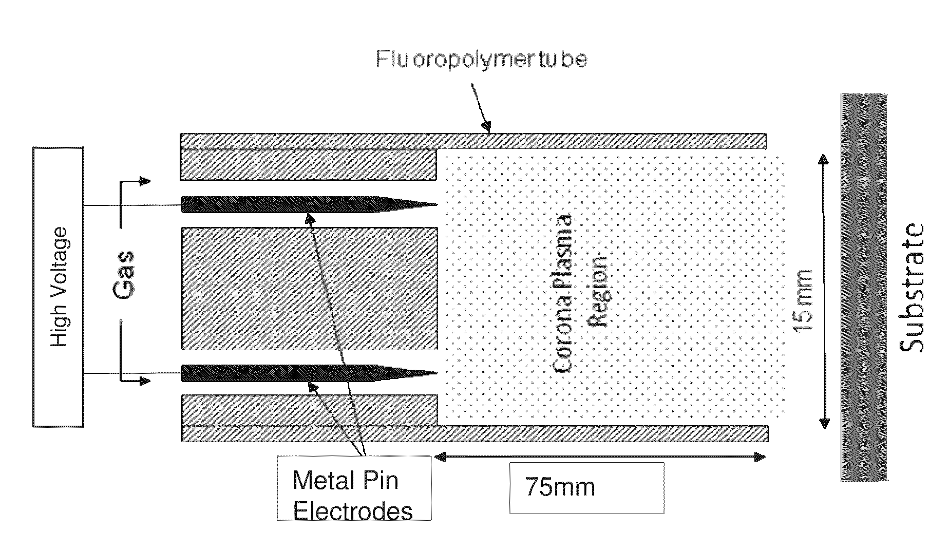
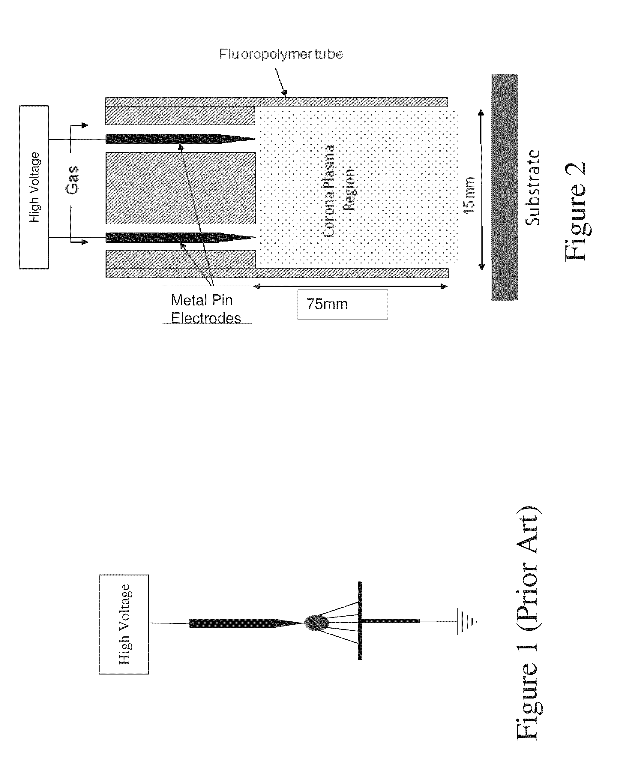
[0046]The invention uses a pin corona plasma at atmospheric pressure to achieve soft polymerization with gas state precursors. The electrode can comprise a single sharp pin as shown in FIG. 1 or two or more pins. For example, FIG. 2 shows a schematic of a two pin electrode head of a pin corona coating system which could be used for the present invention. The dimensions provided in FIG. 2 are by way of illustration only and can differ depending upon the details of the system and application.

[0047]Preferably, although not necessarily, the electrode head comprises a tubular dielectric housing (hatched in FIG. 2) mounting two tungsten needle pointed electrodes to which are applied in parallel an alternating current high voltage to generate the corona discharge from the needle tips. A space around each electrode allows a mixture of carrier gas and precursor vapour to enter the device. The carrier gas can be, in principle, any gas but it has been found that relatively chemically inert gas...


PUM

PropertyMeasurementUnit
Frequencyaaaaaaaaaa
Frequencyaaaaaaaaaa
Fractionaaaaaaaaaa

Abstract

A method for deposition of functional coatings comprises igniting a non-thermal equilibrium plasma within an ambient pressure plasma chamber having a gas supply inlet and a plasma outlet; and providing a substrate to be coated adjacent to the plasma outlet. A gas phase pre-cursor monomer is provided to the plasma chamber through the gas inlet. A specific energy is coupled into the plasma during the flow of the pre-cursor through the chamber sufficient to disassociate at least the weakest intra-molecular bond required to allow polymerisation of the pre-cursor when deposited on a surface of the substrate adjacent the plasma outlet, the coupled specific energy not exceeding a specific energy required break intra-molecular bonds required for the functionality of the monomer molecule.

Description

RELATED APPLICATIONS[0001]This application claims the benefit of priority under 35 U.S.C. §365(c) to International Application PCT / EP2010 / 001703, filed Mar. 18, 2010, which claims priority to IE2009 / 0213, filed Mar. 19, 2009, both incorporated herein by reference in entirety.FIELD OF THE INVENTION[0002]The present invention relates to an apparatus and method for deposition of functional coatings.BACKGROUND[0003]In general there are two plasma types, namely thermal equilibrium and non-isothermal equilibrium plasmas. Thermal equilibrium plasmas are typically hot with temperatures ˜10,000 K and are used in industry as plasma torches, jets and arcs for welding, metallurgy, spray coating, etc.[0004]Non-isothermal plasmas are generally cool and can be employed in manufacturing processes including surface cleaning (removal of unwanted contaminants), etching (removal of bulk substrate material), activation (changing surface energies) and deposition of functional thin film coatings onto surf...

Claims


Application Information

Patent Timeline
IPC IPC(8): C23C16/50C23C16/455A61F2/04A61K9/00C12M1/00B32B9/02C23C16/56B32B1/08
CPCB05D1/62Y10T428/1393C23C16/513Y10T428/31971
Inventor HERBERT, ANTHONYJAROSZYNSKA-WOLINSKA, JUSTYNAO'NEILL, LIAM
Owner HERBERT ANTHONY
Why Eureka
Try Eureka