
Electrophoresis Chip and Electrophoresis Apparatus

a technology of electrophoresis apparatus and electrophoresis chip, which is applied in the direction of diaphragms, biological testing, peptides, etc., can solve the problems of poor processing capability of hplc methods, low accuracy in determining risks, and large cost of analysis apparatus, etc., to achieve accurate analysis of glycosylated hemoglobin, short analysis time, and high accuracy

Inactive Publication Date: 2012-01-19
SUGIYAMA KOJI +2
View PDF6 Cites 8 Cited by
  • Summary
  • Abstract
  • Description
  • Claims
  • Application Information

AI Technical Summary

Benefits of technology

The present invention provides electrophoresis chips for analyzing glycosylated hemoglobin by capillary electrophoresis. These chips have a small size and short analysis time, and can accurately analyze glycosylated hemoglobin. This allows for accurate analysis of glycosylated hemoglobin in POC testing and management of risks due to complications. The electrophoresis chips have a substrate with a plurality of fluid reservoirs and a capillary channel for sample analysis. The first introduction reservoir and the first recovery reservoir are formed in the substrate and are in communication with each other via the capillary channel for sample analysis.

Problems solved by technology

Although immunological methods and enzymatic methods are generally used in processing and analyzing large numbers of specimens, they are of low accuracy when determining the risks due to complications.
On the other hand, although HPLC methods have a poorer processing capability than immunological methods or enzymatic methods, they are useful in determining the risk of complications.
However, due to the configuration of HPLC methods, the analysis apparatus is very large and costly.
This method, however, uses a fused silica capillary having an inner diameter of 25 μm, which is not advantageous in terms of sensitivity, and requires an analysis time of about 4 minutes for the analysis of HbA1c.
Moreover, this method requires the use of a large electrophoresis apparatus.
In addition, POC (point of care) testing using any of the aforementioned conventional methods is not sufficiently accurate to enable the management of the risks due to complications, and it has been used as no more than a screening test.

Method used


Image

  • Electrophoresis Chip and Electrophoresis Apparatus
  • Electrophoresis Chip and Electrophoresis Apparatus
  • Electrophoresis Chip and Electrophoresis Apparatus

Examples


embodiment 1

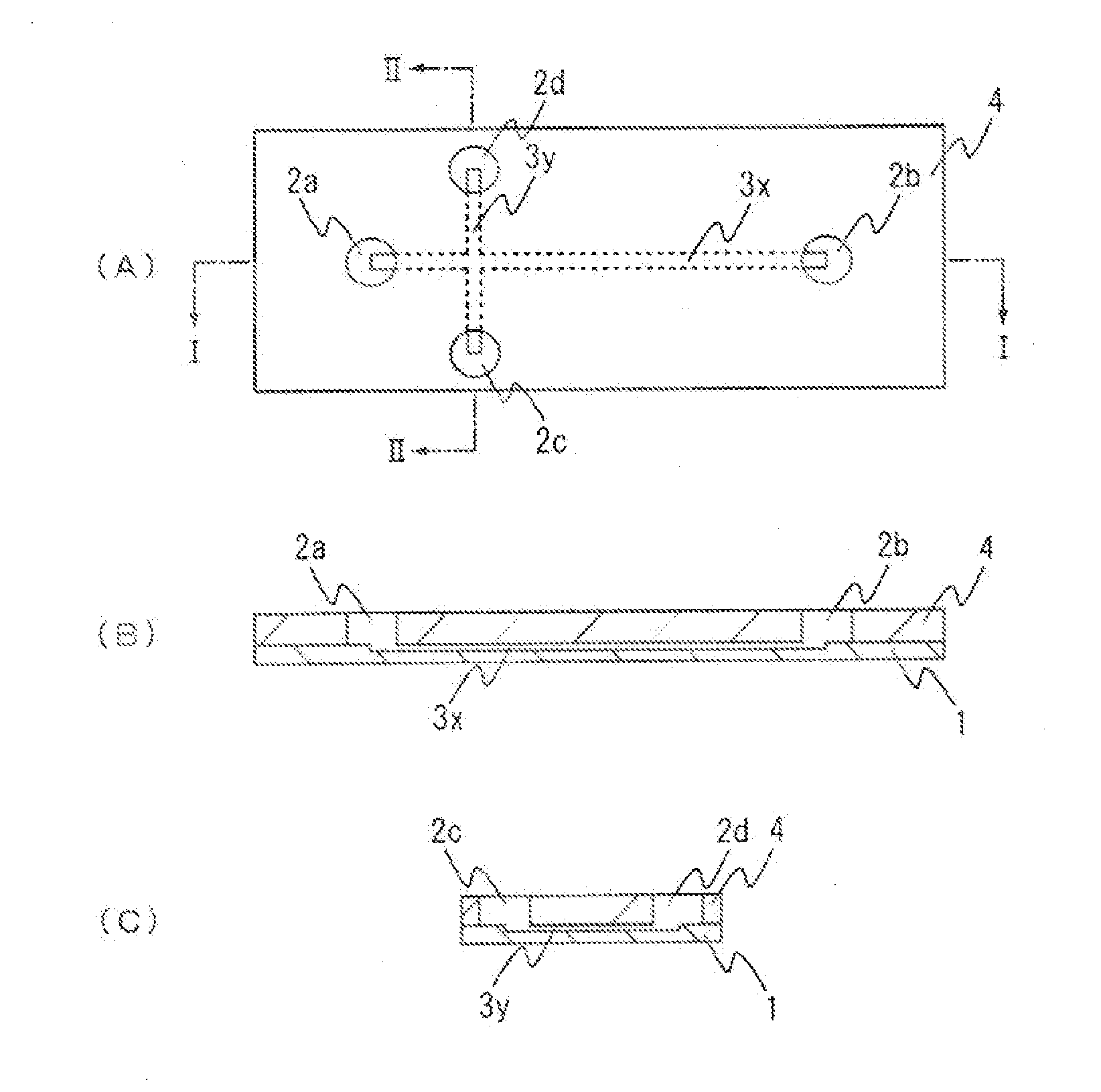
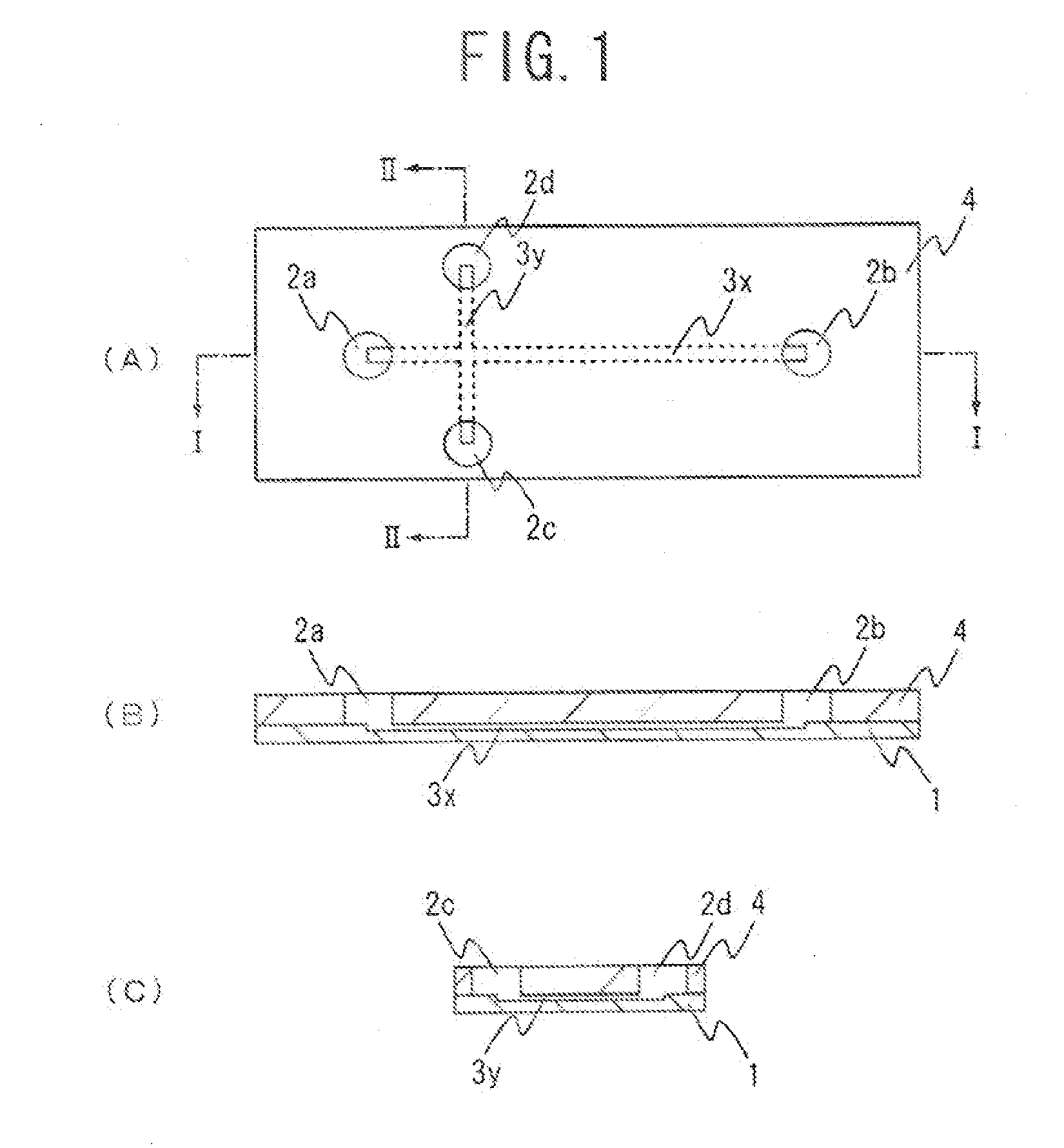
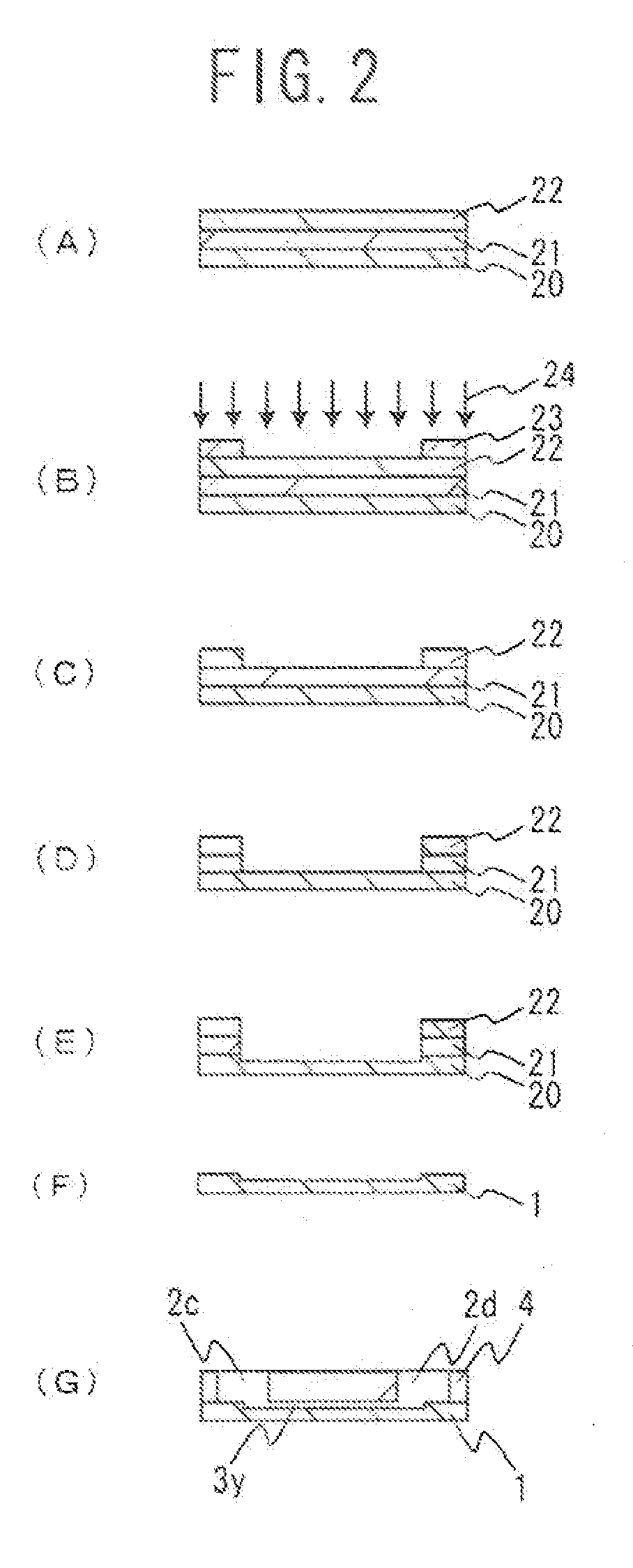
[0044]FIG. 1 shows an example of an electrophoresis chip of the present invention. FIG. 1(A) is a plan view of an electrophoresis chip of this embodiment, FIG. 1(B) is a cross-sectional view when taken along I-I of FIG. 1(A), and FIG. 1(C) is a cross-sectional view when taken along II-II of FIG. 1(A). For easier understanding, the size, proportions and like features of each component in the illustrations are different from the actual features of each component. This electrophoresis chip is, as shown in the figures, configured such that an upper substrate 4 is laminated onto a lower substrate 1. A plurality of through-holes (four in this embodiment) is formed in the upper substrate 4. The bottom parts of the four through-holes formed in the upper substrate 4 are sealed with the lower substrate 1 and, thus, fluid reservoirs 2a to 2d are formed. A cross-shaped groove is formed in the lower substrate 1. By sealing the upper part of the cross-shaped groove formed in the lower substrate 1...

embodiment 2

[0084]FIG. 7 shows another example of an electrophoresis chip of the present invention. In FIG. 7, the portions that are identical to those in FIG. 1 are given the same numbers and symbols. In an electrophoresis chip of this embodiment, a plurality of concave portions (four in this embodiment) and a cross-shaped groove are formed in a substrate (lower substrate) 1. A surface of the substrate (lower substrate) 1 is sealed with a sealing material (upper substrate) 4 that has openings at places corresponding to the four concave portions. The four concave portions formed in the substrate (lower substrate) 1 serve as four fluid reservoirs 2a to 2d. By sealing the upper part of the cross-shaped groove formed in the substrate (lower substrate) 1 with the sealing material (upper substrate) 4, a capillary channel for sample analysis 3x and a capillary channel for sample introduction 3y are formed. Otherwise an electrophoresis chip of this embodiment is of the same configuration as the electr...

embodiment 3

[0096]FIG. 8 shows still another example of an electrophoresis chip of the present invention. In FIG. 8, the portions that are identical to those in FIG. 1 are given the same numbers and symbols. In an electrophoresis chip of this embodiment, a plurality of through-holes (four in this embodiment) are formed in a substrate (upper substrate) 4. A cross-shaped groove is formed in the bottom surface of the substrate (upper substrate) 4. The bottom surface of the substrate (upper substrate) 4 is sealed with a sealing material (lower substrate) 1. The bottom parts of the four through-holes formed in the substrate (upper substrate) 4 are sealed with the sealing material (lower substrate) 1, and thereby four fluid reservoirs 2a to 2d are formed. By sealing the lower part of the cross-shaped groove formed in the substrate (upper substrate) with the sealing material, a capillary channel for sample analysis 3x and a capillary channel for sample introduction 3y are formed. Otherwise an electrop...


PUM

PropertyMeasurementUnit
thicknessaaaaaaaaaa
thicknessaaaaaaaaaa
widthaaaaaaaaaa

Abstract

An electrophoresis chip that enables an apparatus to be small, analysis time to be short and glycosylated hemoglobin to be analyzed highly accurately is provided. The electrophoresis chip includes an upper substrate 4, a lower substrate 1, a first introduction reservoir 2a, a first recovery reservoir 2b and a capillary channel for sample analysis 3x; the first introduction reservoir 2a and the first recovery reservoir 2b are formed in the lower substrate 1; and the first introduction reservoir 2a and the first recovery reservoir 2b are in communication with each other via the capillary channel for sample analysis 3x.

Description

TECHNICAL FIELD[0001]The present invention relates to an electrophoresis chip and an electrophoresis apparatus.BACKGROUND ART[0002]The degree of glycosylation of various proteins has been analyzed as an indicator that shows the condition of a living body. In particular, since the degree of glycosylation of hemoglobin (Hb), especially HbA1c, in blood cells reflects the history of glucose levels in a living body, it is regarded as an important indicator in the diagnosis, treatment or the like of diabetes. HbA1c is HbA(α2β2) whose β-chain N-terminal valine has been glycosylated.[0003]HbA1c has been analyzed by, for example, immunological methods, enzymatic methods, high-performance liquid chromatography (HPLC) methods, and affinity methods, among others. Although immunological methods and enzymatic methods are generally used in processing and analyzing large numbers of specimens, they are of low accuracy when determining the risks due to complications. On the other hand, although HPLC ...

Claims


Application Information

Patent Timeline
Patent Type & Authority Applications(United States)
IPC IPC(8): G01N27/447G01N33/50
CPCB01L3/50273B01L2300/0867B01L2300/0887G01N27/44791B01L2400/0421C07K1/26B01L2300/16
Inventor SUGIYAMA, KOJIYONEHARA, SATOSHINAKAYAMA, YUSUKE
Owner SUGIYAMA KOJI
Learn More