
Parallel motor drive disable verification system and method

a technology of parallel inverter and verification system, which is applied in the direction of motor/generator/converter stopper, power supply testing, dynamo-electric converter control, etc., can solve the problems of device failure, unique difficulties in parallel inverter applications, and proportional size and cost of such drives

Active Publication Date: 2012-01-19
ROCKWELL AUTOMATION TECH
View PDF8 Cites 27 Cited by
  • Summary
  • Abstract
  • Description
  • Claims
  • Application Information

AI Technical Summary

Benefits of technology

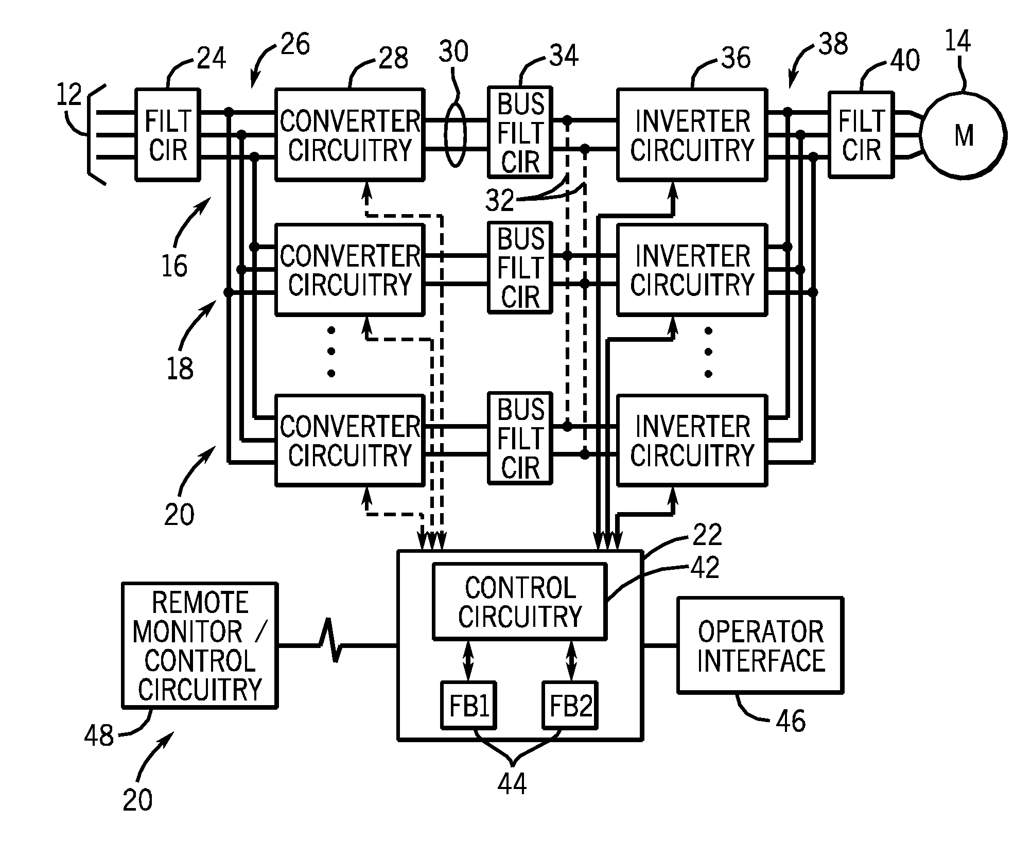
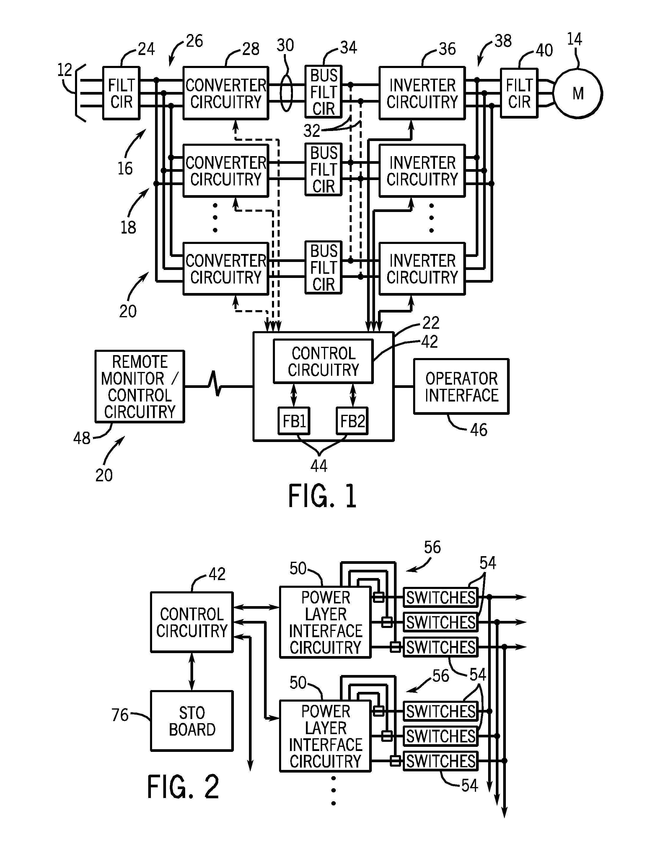
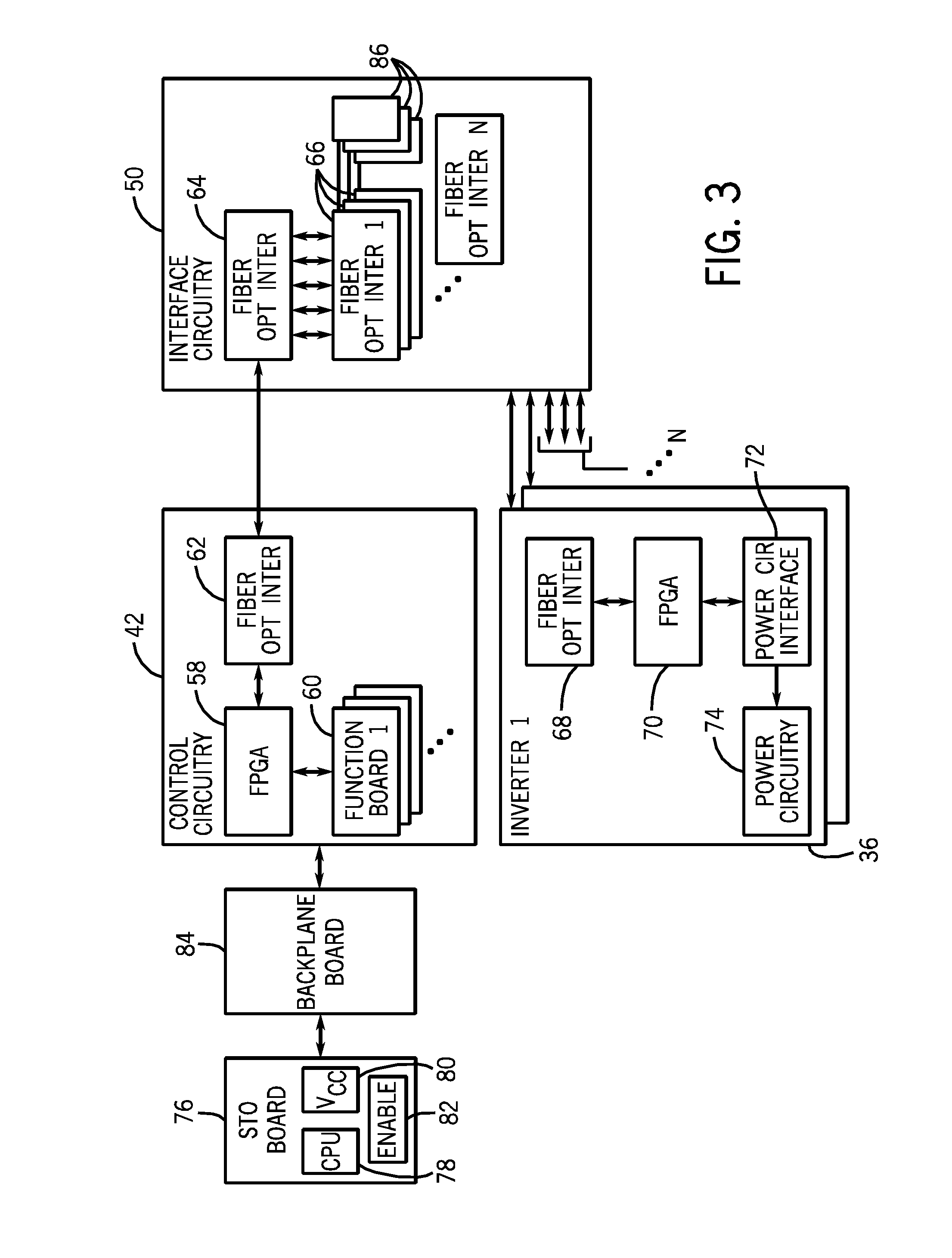
[0006]The present invention relates generally to systems and methods of verifying the proper operation of a shutdown circuitry. Embodiments include systems and methods of reducing or eliminating the electrical stress on motor windings due to a shutdown test pulse from the motor control circuitry that verifies the operability of a shutdown circuitry used in a parallel motor drive configuration. In the embodiments described below, multiple motor drives operating in parallel may be verified for proper shutdown operation by employing fiber optic components to interface the motor control circuitry and each of the parallel motor drives.

Problems solved by technology

However, for larger motors the components of such drives become proportionally large and expensive.
Such parallel inverter applications pose unique difficulties.
However, in some cases, decoupling one motor drive may affect the power delivered to parallel motor drives or to other motor drive circuitry that may be useful even though power is not being delivered to the load.
The shutdown test may, however, tend to stress the power module circuitry or the load device, possibly leading to device failure.
For pulsed motor drives, for example, rapid interruption and re-initiation of a pulse train powering the load can cause high potential differences within and between phase conductors that can lead to degradation of insulating systems, and eventually to failure of the motor or other system component.
Also, interruption of actual drive power to a motor during such verification tests is generally undesirable.
To date, however, reliable disable-verification techniques for parallel motor drives that do not perturb the normal operation of the drive circuitry have yet to be developed or proposed.

Method used


Image

  • Parallel motor drive disable verification system and method
  • Parallel motor drive disable verification system and method
  • Parallel motor drive disable verification system and method

Examples


Embodiment Construction

[0015]Typically, pulse width modulation is used to drive an inverter module for delivering power to a motor. The inverter module includes a set of solid state switches, such as insulated gate bipolar transistors (IGBTs) that are rapidly switched on and off to create an approximately sinusoidal waveform at the output of the inverter. Because the motor is inductive, currents continue to flow even when the power module is disabled by the shutdown test pulse, which can result in the pulsed voltage output changing polarity instantaneously. At the end of the shutdown test pulse, when the power module is enabled, the voltage output can reverse polarity again. Voltage polarity reversals in quick succession could result in a high voltage spike on the motor that may tend to damage motor winding insulation. To avoid this, present embodiments use a shutdown test pulse that is short enough in duration, that the output power from the inverter circuitry remains substantially unaffected.

[0016]Furth...


PUM


Abstract

Systems and methods are provided for performing diagnostic testing for multiple motor drives operating in parallel. In one embodiment, the diagnostic testing may involve determining which of the multiple motor drives are in operation and communicating the active configuration of motor drives to testing circuitry. The testing circuitry generates an enable input signal transmitted to the transistor gates in each of the active motor drives. The testing circuitry also generates a power supply input signal transmitted to a DC to DC converter in each of the active motor drives. The responses to the enable input signal and the power supply input signal are measured to determine safety compliance.

Description

BACKGROUND[0001]The invention relates generally to the field of electrical power converters and inverters. More particularly, the invention relates to techniques for verifying that disable circuitry of parallel motor drives are functioning properly.[0002]Large number of topographies and types of power conversion circuits are known and are in use. Many of these circuits rely upon inverter topologies for converting direct current (DC) power to control frequency alternating current (AC) power. In many topologies a rectifier or other converter is provided to receive incoming AC power, typically from the grid, and to convert the AC power to DC power that is applied to a DC bus used to feed the inverter circuitry. Such topologies are used in a variety of applications, such as for controlling the speed and operating characteristics of motors.[0003]Motor drives utilizing inverter topologies often employ a single converter and single inverter coupled to one another by a single DC bus. Conven...

Claims


Application Information

Patent Timeline
IPC IPC(8): H02H7/08
CPCG01R31/42H02P29/02H02H7/08
Inventor CAMPBELL, ALAN J.
Owner ROCKWELL AUTOMATION TECH
Learn More