Bearing component, rolling bearing, and method for producing bearing component

a technology of bearing components and components, applied in the direction of superimposed coating process, heat treatment apparatus, furnaces, etc., can solve the problems of increasing wear, thermal expansion, warping, etc., and achieves the effect of reducing the amount, reducing the amount, and large fracture toughness valu

Active Publication Date: 2012-01-26
NTN CORP
View PDF17 Cites 13 Cited by
  • Summary
  • Abstract
  • Description
  • Claims
  • Application Information

AI Technical Summary

Benefits of technology

[0052]As is apparent from the above description, the present bearing component, rolling bearing and method of producing the bearing component, that adopt as a source material a steel having a carbon content reduced to be equal to or smaller than 0.3% by mass to ensure a large fracture toughness value, and also having an alloy element added thereto in a reduced amount, and that also provide sufficient wear resistance.

Problems solved by technology

This in turn provides an insufficient oil film, which may result in the rolling element and the race member (an inner ring and an outer ring) having their respective surfaces in metal-to-metal contact with each other and thus increasingly worn.
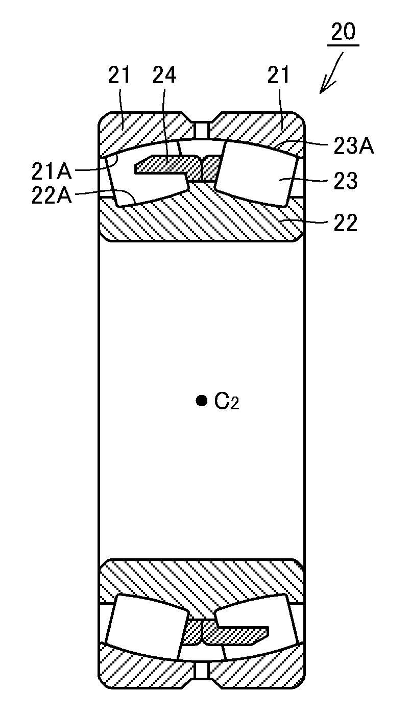
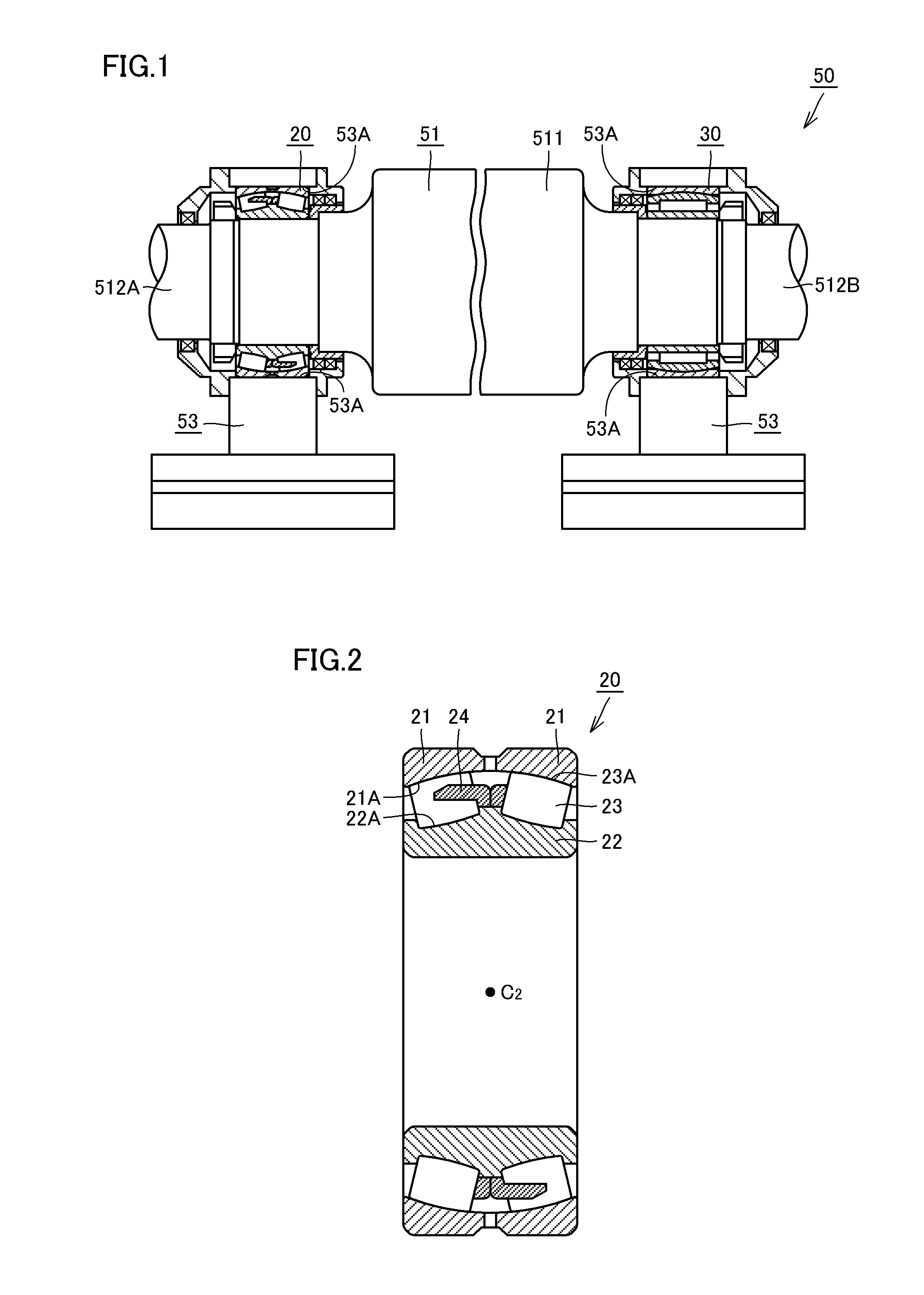
One application in which a rolling bearing is disadvantageously worn, as described above, is for example a self-aligning roller bearing used for a guide roll of equipment operated to continuously cast steel.
The guide roll of such equipment receives melted steel's weight and is exposed to heat of high temperature and thus thermally expands, warps, and / or the like.
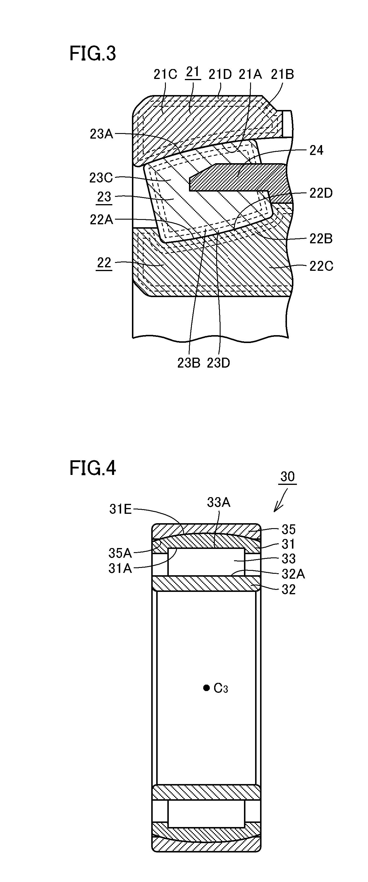
In particular, a self-aligning roller bearing has rollers in the form of barrels and it is thus known to cause differential slip, and a wear difference is caused between a simply rolling portion and a sliding portion and an outer ring raceway surface is partially worn forming two ridges.
The partial wear results in two projections, at which stress concentration arises, and can be a cause of early exfoliation.
Furthermore, melted steel is solidified by coolant water jetted thereto in a large amount, which causes water, vapor and the like to enter the bearing.
However, these bearings are required to have further longer lifetime and simply performing a carbonitriding process does not ensure sufficient wear resistance.

Method used


Image

  • Bearing component, rolling bearing, and method for producing bearing component
  • Bearing component, rolling bearing, and method for producing bearing component
  • Bearing component, rolling bearing, and method for producing bearing component

Examples


example 1

[0100]Hereinafter an example 1 will be described. An experiment was performed to verify a relationship between surface concentration of nitrogen and wear resistance in order to quantitatively verify an effect of nitrogen solved in steel to reduce / prevent wear to know surface concentration of nitrogen required to cause early severe-to-mild wear transition. The experiment was conducted in the following procedure.

[0101]In the experiment, 5 types of steel indicated below in a table 1 were used as source materials. Note that table 1 indicates numerical values each representing an element's content in % by mass. Furthermore, the symbol “−” indicates that the corresponding element is not added and a remainder is formed of iron and an impurity.

TABLE 1type of steelCSiMnNiCrMoVex. A ofSCM 4200.20.30.80.11.2 0.15—presentinventionex. B ofSNCM 4200.20.250.61.60.50.2—presentinventioncomparativeSUJ 21.00.20.40.11.4——ex. AcomparativeSUJ 2 + C1.21.00.30.81.5——ex. Badded steelcomparativeV added0.350....

example 2

[0109]An example 2 will now be described. An experiment was conducted to verify why increased surface concentration of nitrogen leads to increased wear resistance. More specifically, a material was carburized to prepare a test piece and an identical material was carbonitrided to prepare another test piece, and the test pieces underwent a wear test to examine how the amount of each test piece worn varies with time to confirm transition from severe wear to mild wear. The experiment was conducted in the following procedure.

[0110]Initially, JIS SUJ2 and SCM420 were prepared as steel materials serving as source materials, and shaped similarly as done in example 1 to obtain shaped bodies. The SUJ2 shaped body was normally immersion-quenched (or underwent standard quenching) to provide a test piece. The SUJ2 shaped body was also carbonitrided and quenched to provide another test piece. The SCM420 shaped body was carburized and quenched to provide a test piece. The SCM420 shaped body was al...

example 3

[0116]An example 3 will now be described.

[0117]An experiment was conducted to examine a heat treatment method for providing a nitrogen concentration equal to or larger than 0.3% by mass at surfaces of bearing components formed of SCr420, SCM420 and SNCM420 or a similar standard carburizing steel (an alloyed steel for mechanical structure use as defined by JIS G4053).

[0118]Initially, an investigation was conducted to obtain a relationship between a ratio of NH3 introduced into a heat treatment furnace and undecomposed ammonia concentration in the atmosphere internal to the furnace (hereinafter also referred to as in-furnace NH3 gas concentration) for atmospheric temperatures of 850° C. and 940° C. The experiment was conducted with a batch furnace having a volume of 120 L. Furthermore, the atmospheric temperature of 850° C. is a temperature assumed as a temperature applied to carbonitride high carbon chromium bearing steel having a carbon content of approximately 1% by mass (e.g., SUJ...


PUM

PropertyMeasurementUnit
temperatureaaaaaaaaaa
concentrationaaaaaaaaaa
wear resistanceaaaaaaaaaa

Abstract

An outer ring, an inner ring and a roller serving as a bearing component that adopts as a source material a steel ensuring a large fracture toughness value and also having an alloy element added thereto in a reduced amount and also provides sufficient wear resistance, are configured of a steel containing 0.15-0.3% by mass of carbon, 0.15-0.7% by mass of silicon, and 0.15-1.0% by mass of manganese, with a remainder of iron and an impurity, and have a raceway/rolling contact surface included in a region having a carbon enriched layer and a nitrogen enriched layer. In the nitrogen enriched layer the raceway/rolling contact surface has a nitrogen concentration equal to or larger than 0.3% by mass.

Description

TECHNICAL FIELD[0001]The present invention relates generally to bearing components, rolling bearings, and methods for producing bearing components, and particularly to bearing components, rolling bearings, and methods for producing bearing components, that can achieve improved wear resistance.BACKGROUND ART[0002]In recent years, as machines are increasingly reduced in weight and size, the rolling bearings used for the machines are also reduced in size. Accordingly, there is a tendency that contact pressure caused in the rolling bearing (or between a race member and a rolling element) increases. This results in increased temperature, and hence a lubricant degraded and reduced in viscosity. This in turn provides an insufficient oil film, which may result in the rolling element and the race member (an inner ring and an outer ring) having their respective surfaces in metal-to-metal contact with each other and thus increasingly worn. In particular, under such a condition of lubrication t...

Claims


Application Information

Patent Timeline
Patent Type & Authority Applications(United States)
IPC IPC(8): F16C23/08C22C38/02C22C38/08C23C8/32C22C38/24C22C38/44C22C38/46F16C19/22C22C38/22
CPCC21D1/74C23C28/044C22C38/02C22C38/04C22C38/40C22C38/44C22C38/46C23C8/32F16C13/02F16C23/084F16C23/086F16C33/62F16C33/64C23C28/042C21D9/40F16C19/38
Inventor MORI, NOBUYUKI
Owner NTN CORP
Why Eureka
Try Eureka