

Electrically rechargeable, metal-air battery systems and methods
a battery system and metal air technology, applied in the field of electric rechargeable, metal air battery system and methods, can solve the problems of not being versatile or useable as true storage devices, no battery system has been a commercial success, and not being as versatile or practical as existing battery systems, so as to achieve the effect of long life, affordable and practicality
Inactive Publication Date: 2012-01-26
EOS ENERGY STORAGE
View PDF4 Cites 109 Cited by
- Summary
- Abstract
- Description
- Claims
- Application Information
AI Technical Summary
Benefits of technology
[0004]To overcome all of these problems a new electrically rechargeable metal-air system design / chemistry has been provided in accordance with an aspect of the invention. The metal-air cell design incorporates a substantial number of novel and previously unexplored chemical, materials, structural, and design changes. These important changes and modifications will be described in greater detail below. In some embodiments, this metal-air cell may be a zinc-air cell. Independent third party testing to date has verified that the proposed zinc-air cell could be discharged and charged over 200 times with no evidence of air cathode degradation, thus a longer life is expected. Some (or all) of the modifications listed herein may be combined to obtain cell performance with long cycle life that may make this zinc air system affordable and practical.
[0006]Another aspect of the invention is directed to a rechargeable metal air battery cell system comprising a metal electrode; an air electrode; and an aqueous electrolyte solution having a pH in the range of about 3 to about 10, wherein the battery cell system is capable of at least 500 discharge and recharge cycles without physical degradation of the materials or substantial degradation of the battery cell and system's performance.
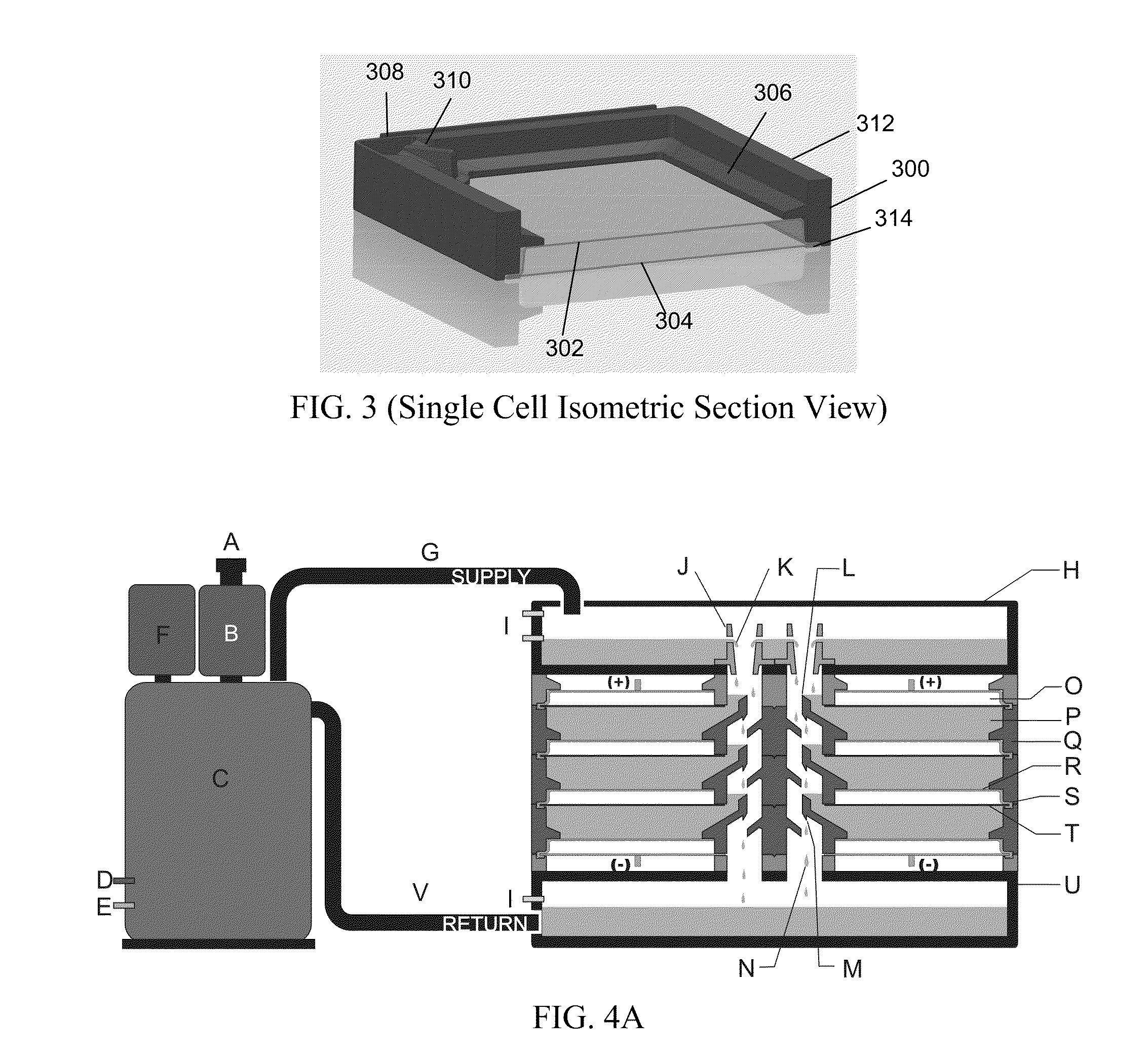
[0009]A method for storing energy may provide another aspect of the invention. The method may comprise receiving an electrolyte at an electrolyte supply tank; allowing, if overflow occurs at the electrolyte supply tank, some electrolyte to fall from an electrolyte supply tank to an underlying first metal-air battery cell; and allowing, if overflow occurs at the underlying metal-air battery cell, some electrolyte to fall from the underlying first metal-air battery cell to a second metal-air battery cell or a collection tank. This electrolyte cascading effect assures that electrolyte levels in all cells are full (to maintain good electrical contact) and approximately equal and level electrolyte volumes even with expansion, contraction or evaporation of electrolyte.
Problems solved by technology
To date no battery system has been a commercial success in this application for several reasons.
One reason is that the cost of existing battery systems is currently too high.
However, they are not as versatile or useable as true storage devices such as batteries.
Current battery cycle life is too low, making true lifetime costs much higher than the initial cost.
Also many batteries (such as sodium-sulfur batteries) operate at elevated temperatures, contain hazardous chemicals, may have flammable materials, or may be subject to runaway reaction such as those occurring in lithium based batteries.
In short, there is no current commercial battery technology that offers large scale battery size, suitable performance, and long discharge / charge cycle life at a commercially viable price and a viable lifetime for utilities.
Method used
View moreImage
Smart ImageViewing Examples

Examples
example
[0315]In one example, a test cell may have been provided. FIG. 13 shows an example of cell voltage over test time in accordance with an embodiment of the invention. A test time of 350000 seconds was provided to demonstrate that the systems works.
[0316]A stable voltage range resulted with the early test cell. There was no physical degradation in the early version of the cell. For example, as shown in FIG. 13, the voltage remained relatively stable for 350000 seconds. For the most part, the voltage cycled between 0.9 and 2.1 volts.
Login to View More PUM
| Property | Measurement | Unit |
|---|---|---|
| fixed distance | aaaaa | aaaaa |
| hydrophobic | aaaaa | aaaaa |
| corrosion | aaaaa | aaaaa |
Abstract
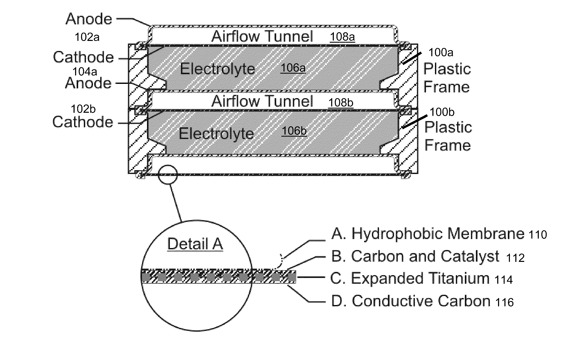
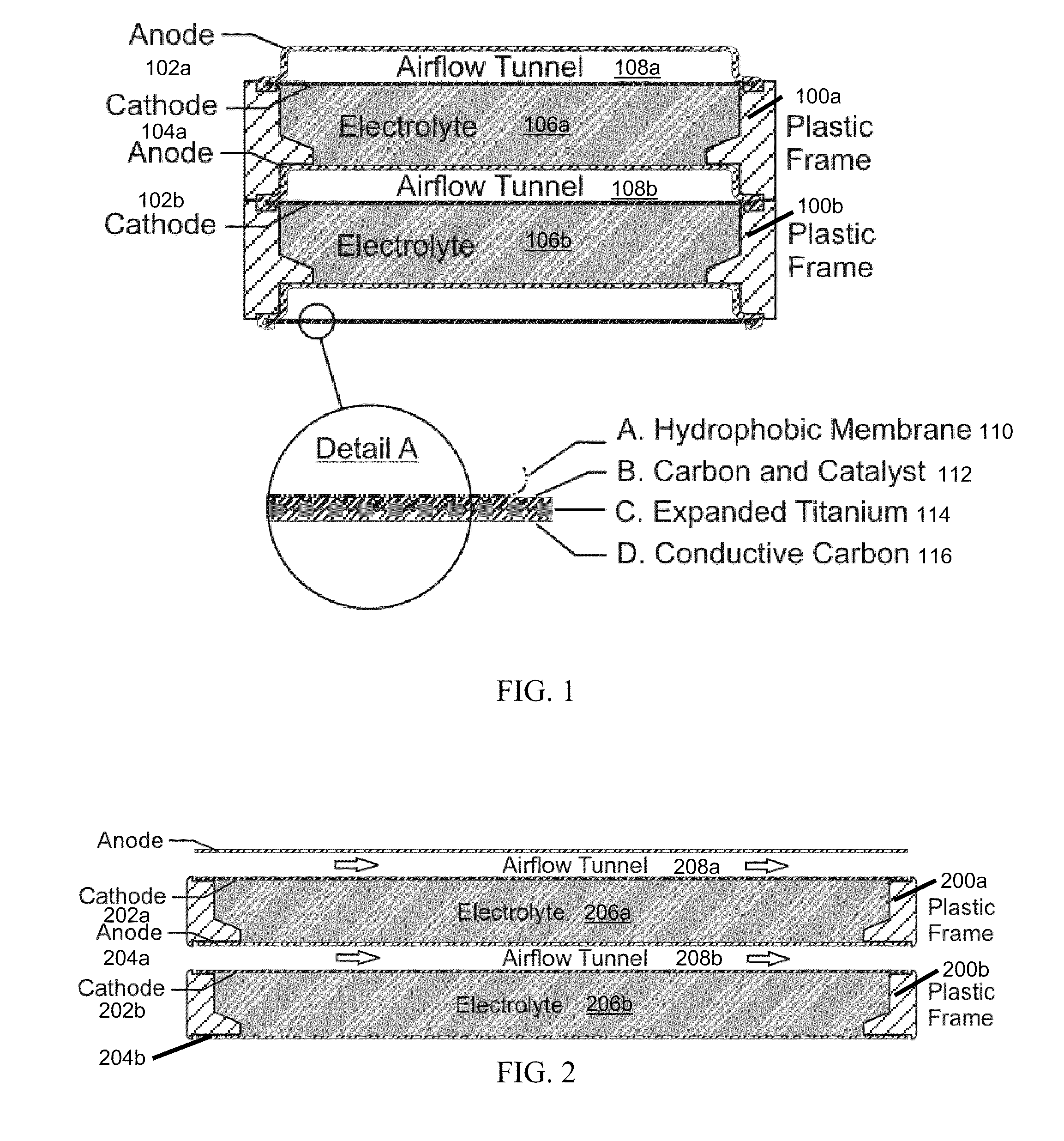
The invention provides for a fully electrically rechargeable metal-air battery systems and methods of achieving such systems. A rechargeable metal air battery cell may comprise a metal electrode an air electrode, and an aqueous electrolyte separating the metal electrode and the air electrode. In some embodiments, the metal electrode may directly contact the electrolyte and no separator or porous membrane need be provided between the air electrode and the electrolyte. Rechargeable metal air battery cells may be electrically connected to one another through a centrode connection between a metal electrode of a first battery cell and an air electrode of a second battery cell. Air tunnels may be provided between individual metal air battery cells. In some embodiments, an electrolyte flow management system may be provided.
Description
BACKGROUND OF THE INVENTION[0001]With a combination of an aging electrical grid infrastructure and integration of intermittent generation sources that come from large scale renewable energy resources such as wind, solar, and ocean waves, there is an increasing and critical need to develop effective energy storage technologies to achieve power supply stability of the grid and to shift electric power supply during peak and off peak periods. Utilities are looking for ways to help add clean power to the grid, prevent power outages and manage peak loads in a cost effective way without adding additional generating capacity. Batteries are considered critical elements in the expansion and large-scale adoption of renewable energy sources such as wind power and solar farms.[0002]To date no battery system has been a commercial success in this application for several reasons. One reason is that the cost of existing battery systems is currently too high. Consequently, utilities primarily use gas...
Claims
Login to View More Application Information
Patent Timeline
 Patent Type & AuthorityApplications(United States)
IPC IPC(8): H01M8/22
CPCH01M4/42H01M4/96H01M12/065Y10T29/49108H01M12/08Y02E60/50H01M2300/0002Y02E60/10H01M50/70
InventorAMENDOLA, STEVENBINDER, MICHAELBLACK, PHILLIP J.SHARP-GOLDMAN, STEFANIEJOHNSON, LOISKUNZ, MICHAELOSTER, MICHAELCHCIUK, TESIAJOHNSON, REGAN
OwnerEOS ENERGY STORAGE