System and method for determining a position of a movable object, arrangement of general lighting LED and light sensor for a position determination of a movable object

a technology of movable objects and systems, applied in the direction of position fixation, wave based measurement systems, instruments, etc., can solve the problems of not monitoring the same permanently and in real time, enabling punctual detection of the stream of goods, and blurring of the signal edges of modulated led lights, so as to achieve simple technical realization, increase communication security, and reduce the effect of eavesdropping

Active Publication Date: 2012-01-26
FRAUNHOFER GESELLSCHAFT ZUR FOERDERUNG DER ANGEWANDTEN FORSCHUNG EV
View PDF5 Cites 30 Cited by
  • Summary
  • Abstract
  • Description
  • Claims
  • Application Information

AI Technical Summary

Benefits of technology

[0020]Fluorescence LEDs are clearly cheaper than RGB LEDs. Apart from that, fluorescence LEDs are by far more common, both for general illumination purposes and also with respect to their use in consumer products. Apart from that, by the use of the fluorescence LEDs and a light wavelength range for signal transmission common to all LEDs and light sensors, embodiments of the invention enable not only savings due to the low costs of the individual fluorescence LEDs compared to the individual RGB LEDs, but also because only one single light sensor is needed, as in contrast to that the above described position finding systems having four different light wavelengths also need four different light sensors. Embodiments of the invention thus use fluorescence LEDs which are of the same construction and / or generally generate light in the same wavelength range or at least light having basically overlapping wavelength ranges.
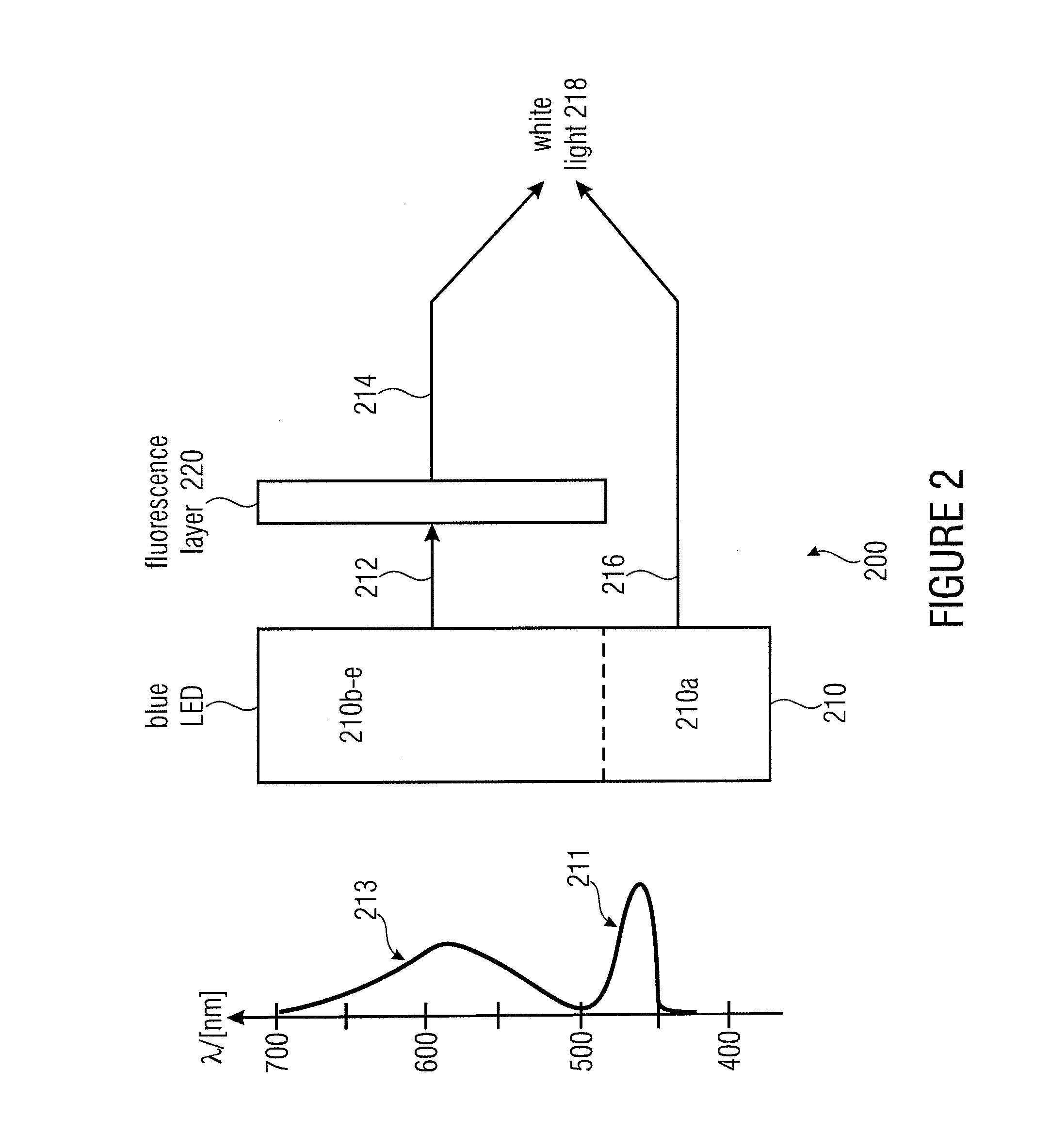
[0021]Further embodiments restrict the spectrum at the detector or light sensor to the directly generated light portion, for example the blue excitation wavelength in a range from 420 nm to 490 nm to enable a more exact position finding. Such embodiments are based on the finding that the absorption of the direct radiation and new emission of the direct radiation or the indirect light portion as compared to the directly generated light portion causes delays in the range of some nanoseconds, and thus the signal edges of the modulated LED light become temporarily blurred, i.e. washy. By the evaluation of the directly generated light portions, for example the blue light portions, a generation and detection of temporally sharper defined signal edges becomes possible and thus also, as mentioned above, a temporally more accurate determination of the signal edges, or generally a temporally more accurate resolution of the signals and signal courses becomes possible and then again a more exact position determination. Apart from that, this also enables a higher data transmission rate.
[0023]Further embodiments of the invention, for example, use RGB-LEDs as general lighting LEDs, each comprising different LED elements, each generating light or a light portion of a different wavelength range, i.e. a different color in the visible light spectrum, wherein the LED elements and their specific color light portions are selected so that a combination or mixture of these light portions results in the desired light or the desired light tone, e.g. white light. The LED elements of the RGB LEDs directly generate the respective color light portion, i.e. without a fluorescence layer. With RGB LEDs the white light is mixed from a combination of a red, a green and a blue directly generated light portion. Other light tones or light of a different color, e.g. the above mentioned pastel shade colored light may, for example, be generated by a mixture of directly generated red, green and blue light portions of other wavelengths. With embodiments of the invention, in which RGB LEDs are used, for example the excitation current of only one of the LED elements is modulated to generate the signal for locating. With an arrangement of general lighting LEDs with RGB LEDs, all three (or more, if more than three general lighting or RGB LEDs are used for position determination) for example transmit the signal for the position determination in the same or at least an overlapping wavelength range, for example in the green, red or blue wavelength range. Advantageously, all RGB LEDs transmit the position signal only in the blue wavelength range (420 nm to 490 nm), as the same enable a more accurate temporal resolution and thus a more accurate locating due to the higher frequency.
[0029]Further, embodiments of the present invention enable a simple extension by additional fluorescence LEDs and thus an increase of the location resolution or accuracy of position determination. This applies both for the embodiments based on a constructive interference and also for the embodiments using a time multiplex method.
[0032]Compared to conventional systems, in which the three above mentioned functionalities are realized in separate systems, embodiments of the present invention for example need no additional hardware components compared to purely optical data transmission systems. From this, clear cost advantages and simple possibilities of technically realizing locating and security features result without affecting the size of devices.
[0033]The combination of the 
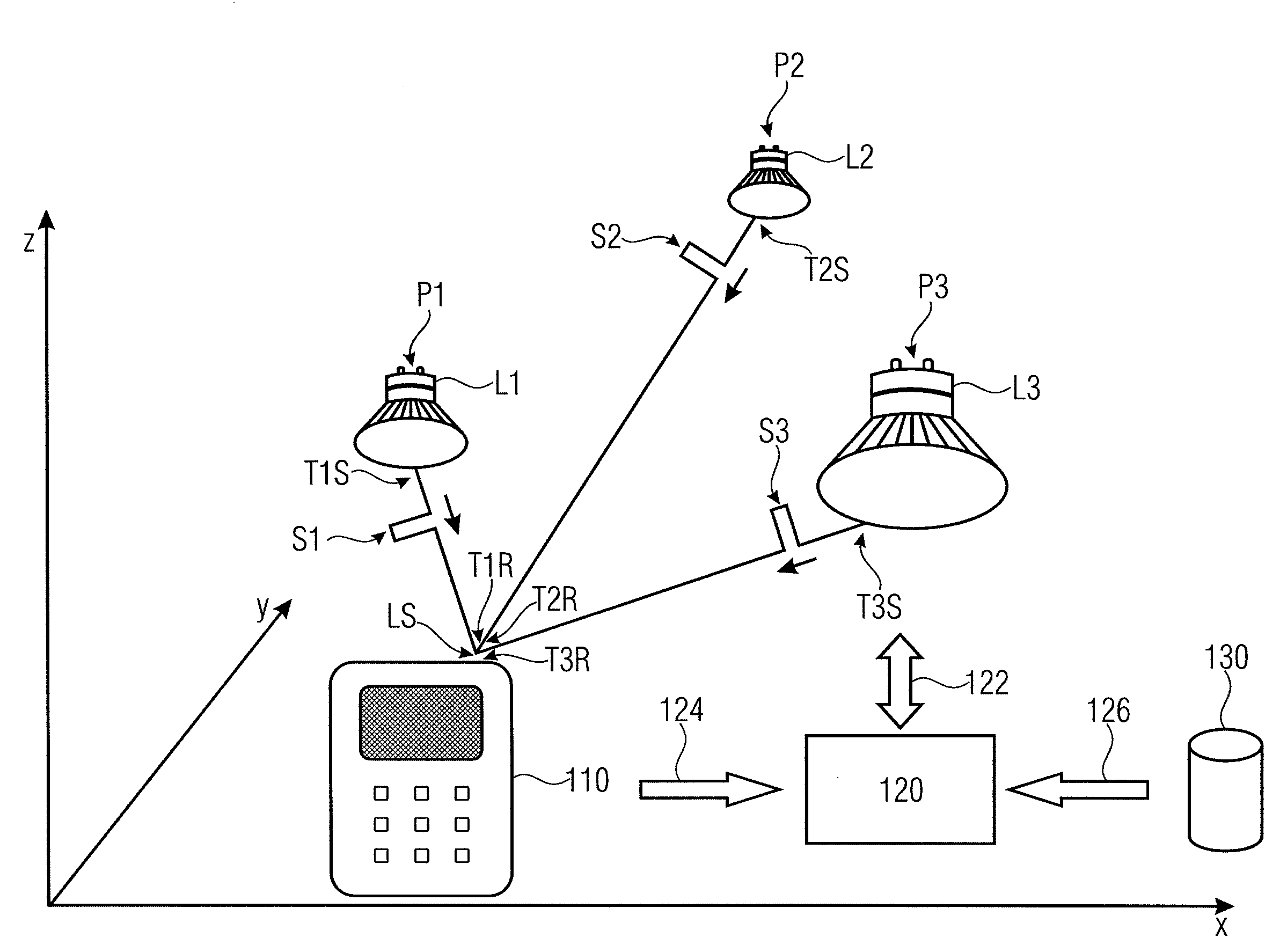
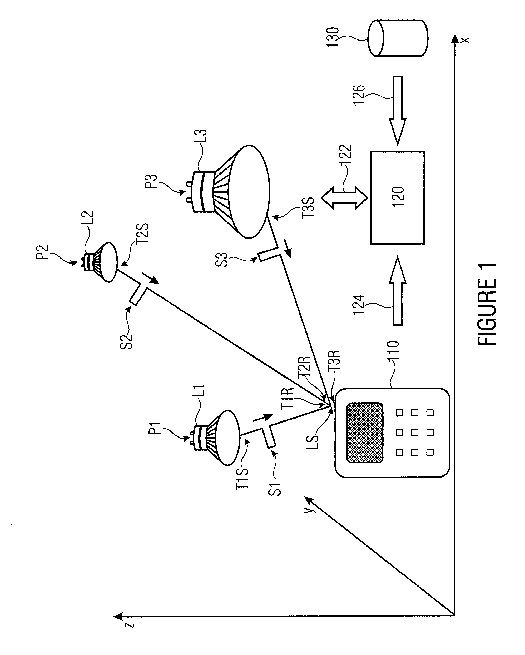
data transmission with light and the position determination with light additionally enable new security functions as such solutions enable to make data streams available specifically at freely defined locations based on the visual contact needed for communication between LED and light sensor and to cut off non-admitted locations from data streams. Thus, the security against eavesdropping of the communication may be substantially increased, as the location of the receiver may be determined from the optical signals with a high accuracy. In other words, embodiments of the present invention enable a clearly increased security in communication, as the transmission protocols may provide data specifically at defined locations.

Problems solved by technology

Such embodiments are based on the finding that the absorption of the direct radiation and new emission of the direct radiation or the indirect light portion as compared to the directly generated light portion causes delays in the range of some nanoseconds, and thus the signal edges of the modulated LED light become temporarily blurred, i.e. washy.
These approaches, however, only enable a punctual detection of the stream of goods and may not monitor the same permanently and in real time.
In security technology, data connections secure against eavesdropping may be set up which may also be limited within the reach of the optical radiation.

Method used


Image

  • System and method for determining a position of a movable object, arrangement of general lighting LED and light sensor for a position determination of a movable object
  • System and method for determining a position of a movable object, arrangement of general lighting LED and light sensor for a position determination of a movable object
  • System and method for determining a position of a movable object, arrangement of general lighting LED and light sensor for a position determination of a movable object

Examples


Embodiment Construction

[0042]In the following description of the embodiments, for like or seemingly like elements the same reference numerals are used.

[0043]In the following, embodiments with fluorescence LEDs as general lighting LEDs are described. The explanations, however, apply accordingly for other embodiments for example with RGB LEDs as general lighting LEDs.

[0044]FIG. 1 shows a schematical illustration of an embodiment of a system for determining a position of a moving object 110, wherein the system comprises an arrangement of three fluorescence LEDs L1 , L2 and L3, a light sensor LS mounted to the moving object and an evaluation unit 120. Optionally, the system may also comprise a data base 130.

[0045]The fluorescence LEDs L1 to L3 are, for example, integrated in the ceiling, a wall or other objects of the environment or mounted to the same and each have a defined, known and fixed position P1 to P3. The positions P1 to P3 are different for example to be able to determine the position of the object...


PUM


Abstract

A system for determining a position of a moving object is described, having: an arrangement having at least three general lighting LEDs, wherein each of the general lighting LEDs is implemented to transmit one light signal each with a transmission time information and a transmitter information, wherein the wavelength ranges of the general lighting LEDs for the signal transmission overlap, wherein the transmitter information enables at least a determination of a position of the respective general lighting LEDs and the transmission time information is information on a point in time when the respective signal was transmitted; a light sensor mounted to the moving object and implemented to receive the light signals and allocate one signal receive time each; and an evaluation unit which is implemented to determine the position of the object based on the transmitter information, the transmission time information and the receive time information.

Description

CROSS-REFERENCE TO RELATED APPLICATIONS[0001]This application claims priority from German Patent Application No. 102010031629.6-55, which was filed on Jul. 21, 2010, and is incorporated herein in its entirety by reference.BACKGROUND OF THE INVENTION[0002]Embodiments of the present invention relate to systems and methods and their components for position determination of a movable object, and in particular to a position determination by means of light emitting diodes (LED) and corresponding light sensors.[0003]Light emitting diodes (LEDs) gain ever more popularity. More and more, LEDs also replace conventional illuminants, like for example thermal emitters (light bulbs, etc.) and other illuminants, for example generating lights by exciting gases. LEDs enable a fast data transmission by modulation of the excitation current of the LEDs. Thus, the LEDs are substantially different from the above-mentioned conventional illuminants also with respect to their serviceability and fields of us...

Claims


Application Information

Patent Timeline
Patent Type & Authority Applications(United States)
IPC IPC(8): G01B11/14G06F15/00
CPCG01S5/16G01S1/70
Inventor GIESEKUS, JOACHIM
Owner FRAUNHOFER GESELLSCHAFT ZUR FOERDERUNG DER ANGEWANDTEN FORSCHUNG EV
Why Eureka
Try Eureka