Method For Processing Hydrocarbon Pyrolysis Effluent

a technology of hydrocarbon pyrolysis and effluent, which is applied in the direction of hydrocarbon oil treatment products, effluent separation, gaseous mixture working up, etc., can solve the problems of ineffective heat transfer, limited outlet temperature on the process side of the tle, and only a portion of furnace effluent heat recovery

Inactive Publication Date: 2012-02-02
EXXONMOBIL CHEM PAT INC
View PDF6 Cites 25 Cited by
  • Summary
  • Abstract
  • Description
  • Claims
  • Application Information

AI Technical Summary

Problems solved by technology

Below this temperature, conventional heat exchangers should not be used because they foul rapidly from accumulation and thermal degradation of tar on the heat exchanger surfaces.
However, the TLE in typical configurations can only recover a portion of furnace effluent heat, as it is limited by the temperature at which tar begins to condense (i.e., tar dew point).
That is, the outlet temperature on the process side of the TLE is limited by fouling when the dew point is encountered.
As noted above, heavy components in the effluent condense at the tar dew point and foul the TLE surfaces, rendering them ineffective for heat transfer.
The primary fractionator system is a very complex set of equipment that typically includes an oil quench section, a primary fractionator tower and one or more external oil pumparound loops.
The primary fractionator system with its associated pumparounds is the one of the more expensive components in the entire cracking process.
Heat exchangers in the pumparound circuit are necessarily large because of high flow rates, close temperature approaches needed to recover the heat at useful levels, and allowances for fouling.
In addition, the primary fractionator has a number of other limitations and problems.
This effectively requires investment in two heat exchange systems, and imposes two temperature approaches (or differentials) on the removal of heat, thereby reducing thermal efficiency.
Moreover, despite the fractionation that takes place between the tar and gasoline streams, both streams often need to be processed further.
Further, the primary fractionator tower and its pumparounds are prone to fouling.
The pumparound loops are also subject to fouling, requiring removal of coke from filters and periodic cleaning of fouled heat exchangers.
Trays and packing in the tower are sometimes subject to fouling, potentially limiting plant production.
The system also contains a significant inventory of flammable liquid hydrocarbons, which is not desirable from an inherent safety standpoint.

Method used


Image

  • Method For Processing Hydrocarbon Pyrolysis Effluent
  • Method For Processing Hydrocarbon Pyrolysis Effluent
  • Method For Processing Hydrocarbon Pyrolysis Effluent

Examples


Embodiment Construction

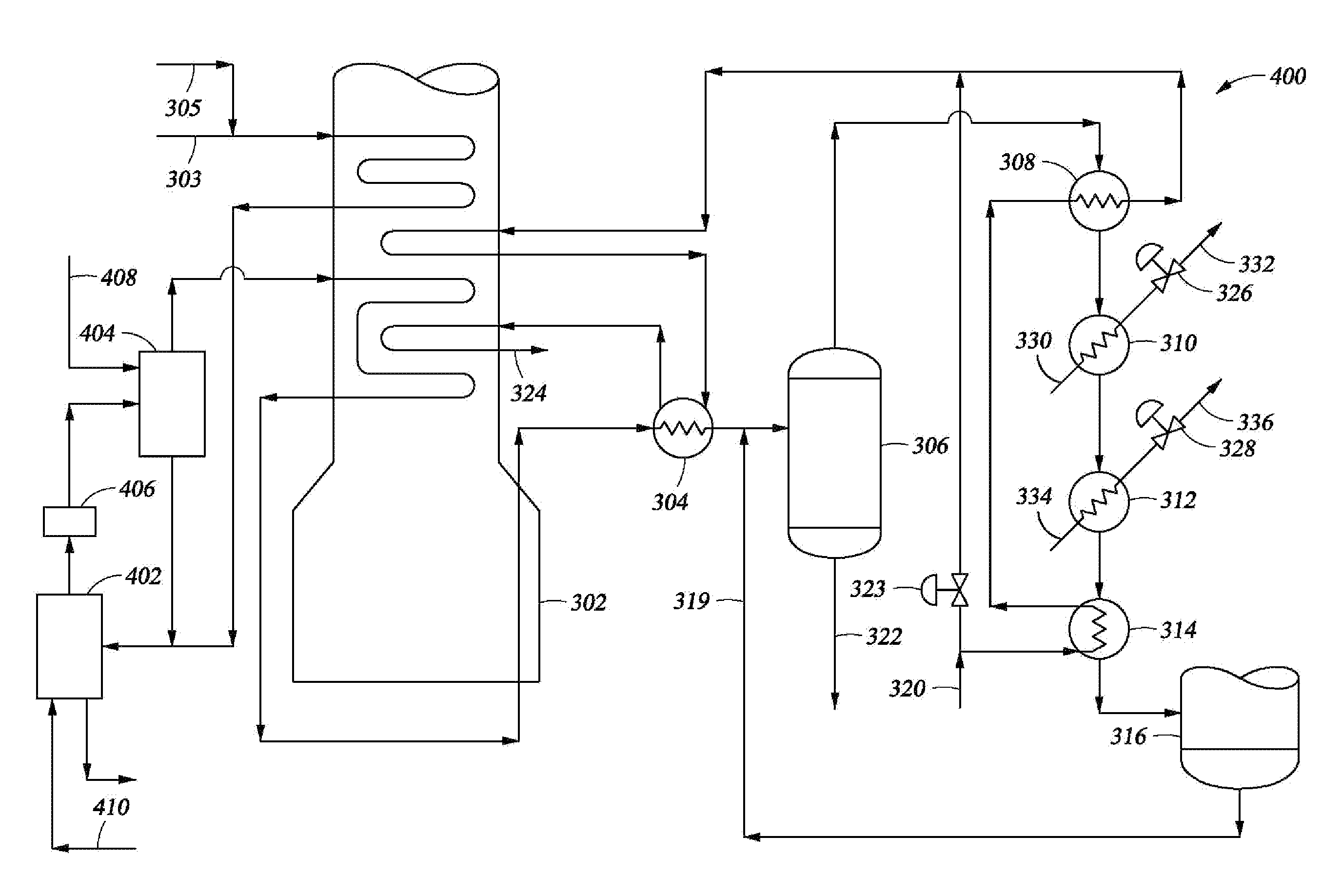
[0024]The present techniques provide an efficient arrangement to treat the effluent stream from a hydrocarbon pyrolysis unit, which may be referred to as a pyrolysis reactor or furnace, so as to remove and recover heat therefrom and to separate desired hydrocarbons. For instance, the present techniques may separate C5+ hydrocarbons, providing separate pyrolysis gasoline, gas oil, quench oil, and tar fractions, as well as the desired C2-C4 olefins in the effluent without utilizing primary fractionator pumparounds.

[0025]Typically, the effluent used in the one or more embodiments of the present techniques is produced by pyrolysis of a hydrocarbon feed boiling in a temperature range from about 40° C. to about 704° C. (about 104° F. to about 1300° F.), such as naphtha, tailed crudes or gas oil. For example, the effluent may be produced by pyrolysis of a hydrocarbon feed having a final boiling point above about 180° C. (about 356° F.), such as a feed heavier than naphtha. Such feeds inclu...


PUM

PropertyMeasurementUnit
outlet temperatureaaaaaaaaaa
pressuresaaaaaaaaaa
pressuresaaaaaaaaaa

Abstract

A method and system are disclosed for treating the effluent from a hydrocarbon pyrolysis unit employing a small primary fractionator. The method comprises cooling the effluent from a furnace through a first heat exchanger, a vapor-liquid separator, and a second heat exchanger before it is passed to a fractionator for further processing. These heat exchangers may also be utilized to heat a utility fluid as part of the cooling process. Further, one or more generators and a third heat exchanger may also be used to assist in heat recovery for the process.

Description

FIELD OF THE INVENTION[0001]The present invention is directed to a method for processing the effluent from hydrocarbon pyrolysis units, especially those units utilizing liquid feeds.BACKGROUND OF THE INVENTION[0002]The production of light olefins (ethylene, propylene and butenes) from various hydrocarbon feedstocks typically utilizes the technique of pyrolysis or steam cracking. Pyrolysis involves heating the feedstock sufficiently to cause thermal decomposition of the larger molecules. Then, the effluent from the cracking furnace may be cooled by using conventional processes or equipment.[0003]This pyrolysis process, however, may produce molecules which tend to combine to form high molecular weight materials known as tars. Tars are high-boiling point, viscous, reactive materials that can foul equipment under certain conditions. The fouling of the equipment should be minimized to avoid inefficiencies and downtime associated with cleaning of the equipment. The formation of tars, afte...

Claims


Application Information

Patent Timeline
Patent Type & Authority Applications(United States)
IPC IPC(8): C10C1/20C10G15/00C10G49/22
CPCC10G9/002C10G2400/20C10G70/041
Inventor STRACK, ROBERT D.ARNOLD, JAMES R.
Owner EXXONMOBIL CHEM PAT INC
Why Eureka
Try Eureka