Extreme ultraviolet light source with a debris-mitigated and cooled collector optics

a collector optics and ultraviolet light source technology, applied in the direction of optical radiation measurement, instruments, therapy, etc., can solve the problem that the common computational fluid dynamics (cfd) code solving the navier-stokes equation cannot be used, and achieve the effect of effectively shielding the collector optics and enhancing its lifetim

Inactive Publication Date: 2012-02-02
ETH ZZURICH
View PDF9 Cites 31 Cited by
  • Summary
  • Abstract
  • Description
  • Claims
  • Application Information

AI Technical Summary

Benefits of technology

[0010]It is an object of this invention to effectively shield the collector optics from the debris (ions and neutrals), thus enhancing its lifetime. It is a further object of the invention to cool the collector optics. At the same time, the chain of droplets should be affe...

Problems solved by technology

A common computational fluid dynamics (CFD) code solving the Navier-Stokes equations cannot be used, because a raref...

Method used


Image

  • Extreme ultraviolet light source with a debris-mitigated and cooled collector optics
  • Extreme ultraviolet light source with a debris-mitigated and cooled collector optics
  • Extreme ultraviolet light source with a debris-mitigated and cooled collector optics

Examples


Embodiment Construction

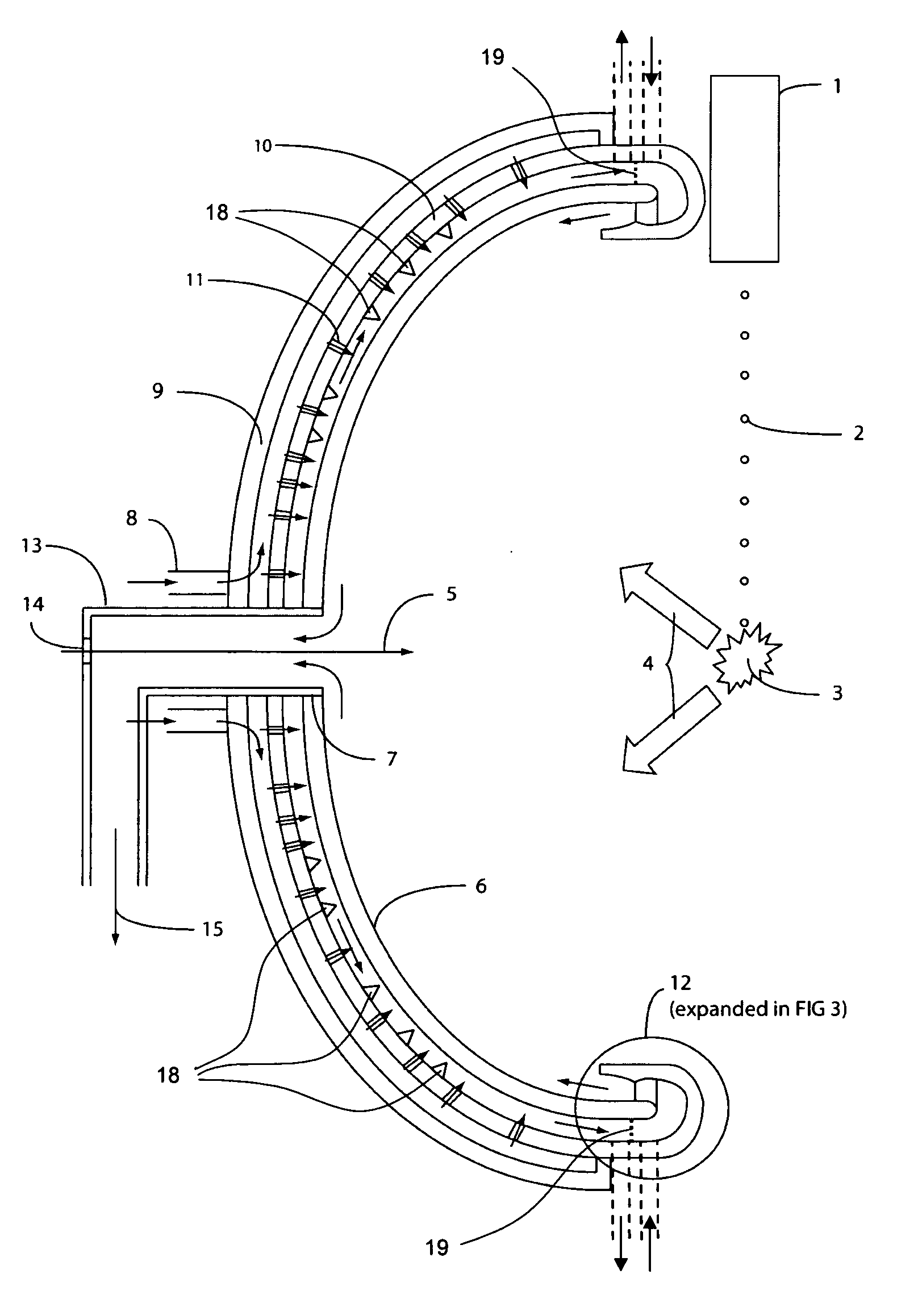
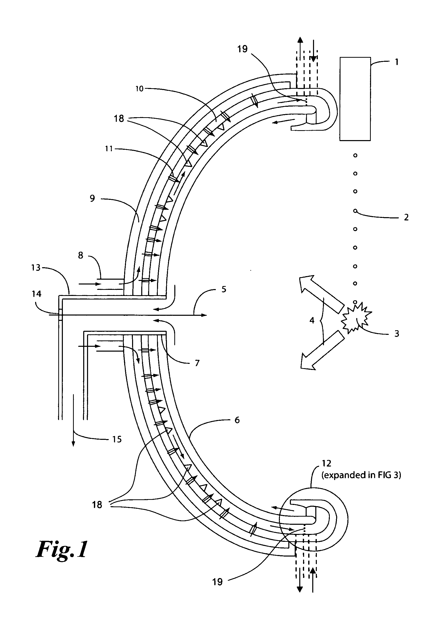
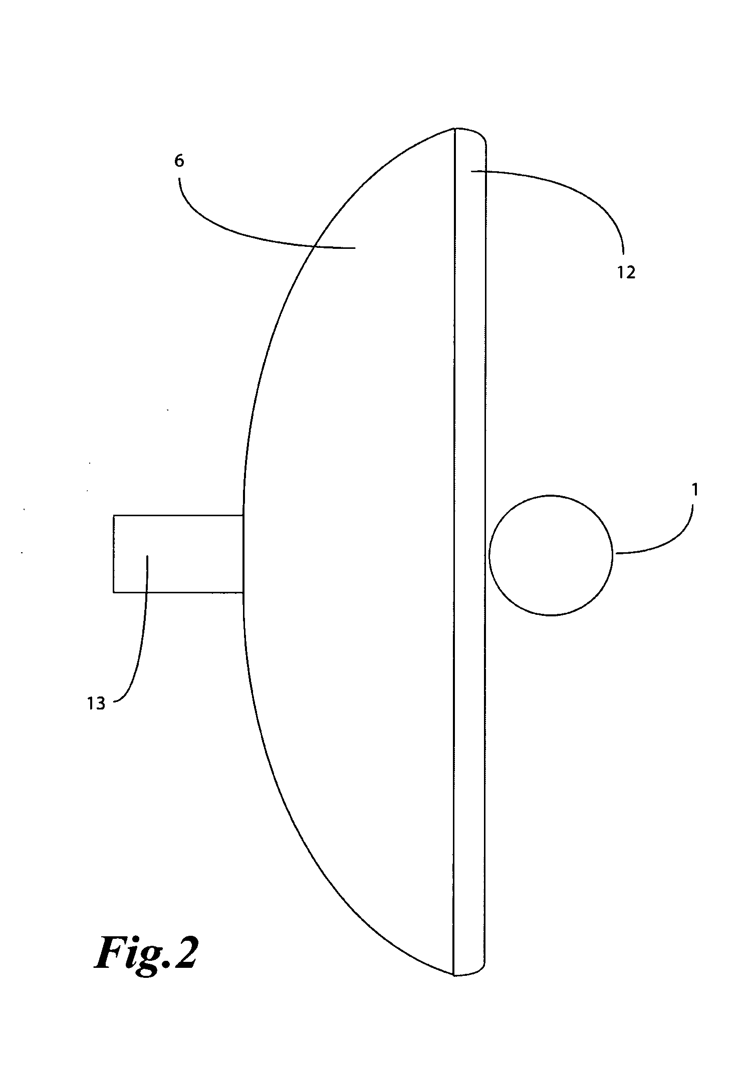
[0039]A preferred embodiment of the EUV source according to the invention is shown in FIG. 1. The elements shown should be sealed in a vacuum chamber, so that the EUV radiation absorption is limited. The EUV source comprises a mass limited target dispenser 1 aligned with a pulsed laser radiation 5. The mass limited targets 2, e.g., droplets, are irradiated by the laser radiation 5 in a EUV production region 3, where EUV light is produced by exciting the droplets 2. Together with the EUV radiation, debris 4 is generated and expands in the direction of a collector optics 6, e.g., a multi-layer mirror. The collector optics 6 is provided with a hole 7 in the middle 7 such that the pulsed laser radiation 5 can pass through.

[0040]The EUV source according to the invention is provided with a debris mitigation system and a cooling of the collector optics 6. A flow of a curtain fluid first passes the internal cooling system and cools the collector optics 6. Then the curtain fluid exits from a...


PUM


Abstract

The extreme ultraviolet light source comprises a production site capable of producing extreme ultraviolet radiation in a laser-produced plasma (3), and a collector optics (6) for collimating the extreme ultraviolet radiation. A pressurized influx of gas forms a gas curtain between the production site and the collector optics (6) in order to protect the collector optics (6) from debris (4) generated at the production site. The gas influx is directed in a way that it follows the surface of the collector optics (6). By thus shielding the collector optics (6) from the debris (4) its lifetime is enhanced. The shielding gas can further be used for cooling the collector optics (6).

Description

BACKGROUND OF THE INVENTION[0001]1. Field of the Invention[0002]The present invention lies in the field of the generation of extreme ultraviolet (EUV) radiation. It refers to an extreme ultraviolet light source according to the preamble of claim 1.[0003]2. Discussion of Related Art[0004]The next generation of semiconductor devices will be manufactured using extreme ultraviolet (EUV) lithography. EUV light is electromagnetic radiation with wavelengths between 120 nm and 10 nm. In EUV sources, a EUV-emitting plasma is produced by irradiating a target material, e.g., tin (Sn). The radiation exciting the target material can be a laser beam, thus producing a laser produced plasma (LPP). The EUV radiation is collected by collector optics, e.g., a collimating mirror, and directed to an intermediate region for utilization outside of the EUV light source.[0005]The debris produced by the EUV emitting laser plasma limits the lifetime of the collector optics and should be mitigated in order to ...

Claims


Application Information

Patent Timeline
IPC IPC(8): G21K5/04
CPCG03F7/70908G03F7/70983G03F7/70916B08B5/00B08B17/02G03F7/203H01L21/0274H05G2/003
Inventor ABHARI, REZAGIOVANNINI, ANDREAROLLINGER, BODBLEINER, DAVIDE
Owner ETH ZZURICH
Why Eureka
Try Eureka