Articles and devices for thermal energy storage and methods thereof

a technology of thermal energy storage and thermal energy, which is applied in the direction of indirect heat exchangers, lighting and heating apparatus, packaging goods types, etc., can solve the problems of more than 30% of the fuel energy supplied to an internal combustion engine (internal combustion engine) being lost to the environment via engine exhaust, and operating inefficiently, so as to achieve high heat storage density, high surface area, and high energy density

Inactive Publication Date: 2012-02-16
DOW GLOBAL TECH LLC
View PDF9 Cites 26 Cited by
  • Summary
  • Abstract
  • Description
  • Claims
  • Application Information

AI Technical Summary

Benefits of technology

[0015]The articles, devices, systems and processes of the present invention advantageously are capable of containing a high concentration of thermal energy storage material so that a large amount of thermal energy can be stored (e.g., having a high energy density), are capable of having a high surface area between the heat transfer fluid and the article containing the thermal energy storage material so that heat can be quickly transferred into and / or out of the thermal energy storage material (e.g., having a high power density, preferably greater than about 8 kW / L), are capable of having multiple flow paths that have similar or equal hydraulic resistance so that heat is uniformly transferred to and / or transferred from different regions; have a rotational symmetry so that they may be arranged easily; have a structure that is strong and durable; have a high heat storage density so that they can be used in applications requiring compact designs, light weight components, or both; have lower hydraulic resistance for a heat transfer fluid flow (for example, a pressure drop of less than about 1.5 kPa at a heat transfer fluid pumping rate of about 10 liters / min) so that the pumping requirements for the heat transfer fluid are reduced, are sufficiently strong so that the thermal energy storage material does not leak from a sealed space after heating a capsular structure including the thermal energy storage material to a temperature of about 400° C., are sufficiently durable so that the thermal energy storage material does not leak from a sealed space after repeatedly heating the capsular structure with the thermal energy storage material between about 25° C. and about 240° C. for about 1,000 cycles or more, or an combination thereof.

Problems solved by technology

Regarding the transportation industry, it is well known that internal combustion engines operate inefficiently.
Sources of this inefficiency include heat lost via exhaust, cooling, radiant heat and mechanical losses from the system.
It is estimated that more than 30% of the fuel energy supplied to an internal combustion engine (internal combustion engine) is lost to the environment via engine exhaust.
It is well known that during a “cold start” internal combustion engines operate at substantially lower efficiency, generate more emissions, or both, because combustion is occurring at a non-optimum temperature and the internal combustion engine needs to perform extra work against friction due to high viscosity of cold lubricant.
This problem is even more important for hybrid electric vehicles in which the internal combustion engine operates intermittently thereby prolonging the cold start conditions, and / or causing a plurality of occurrences of cold start conditions during a single period of operating the vehicle.
However, in order to provide a long term (e.g., greater than about 6 hour) heat storage capability, they generally occupy a large volume, require pumping of a large volume of heat transfer fluid, require a relatively large pump to overcome the hydraulic resistance, and the like.
The issue of packaging of the thermal energy storage materials for applications requiring systems that are light weight, such as in transportation, requires both strong packaging and packaging that is light weight.

Method used


Image

  • Articles and devices for thermal energy storage and methods thereof
  • Articles and devices for thermal energy storage and methods thereof
  • Articles and devices for thermal energy storage and methods thereof

Examples


examples

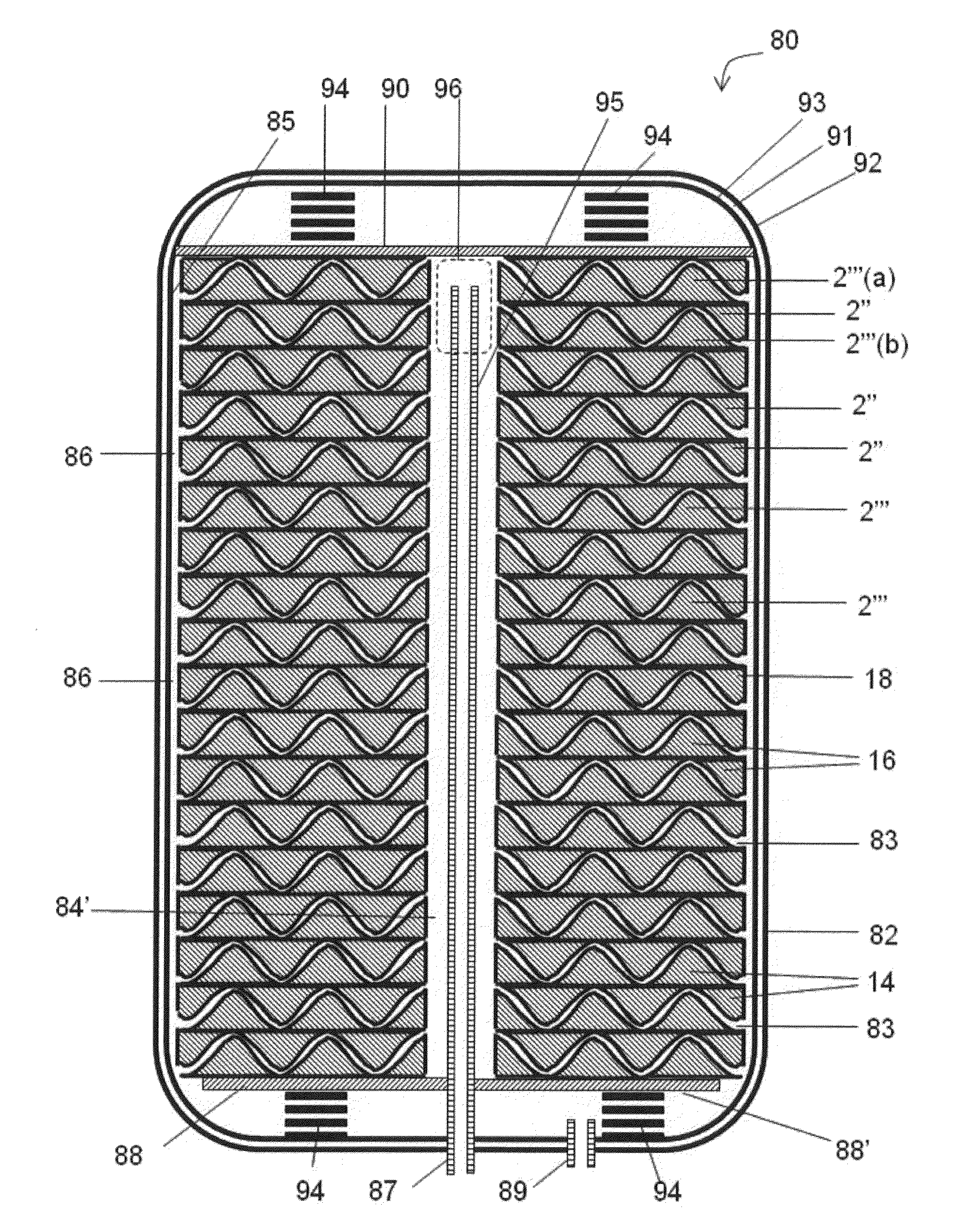
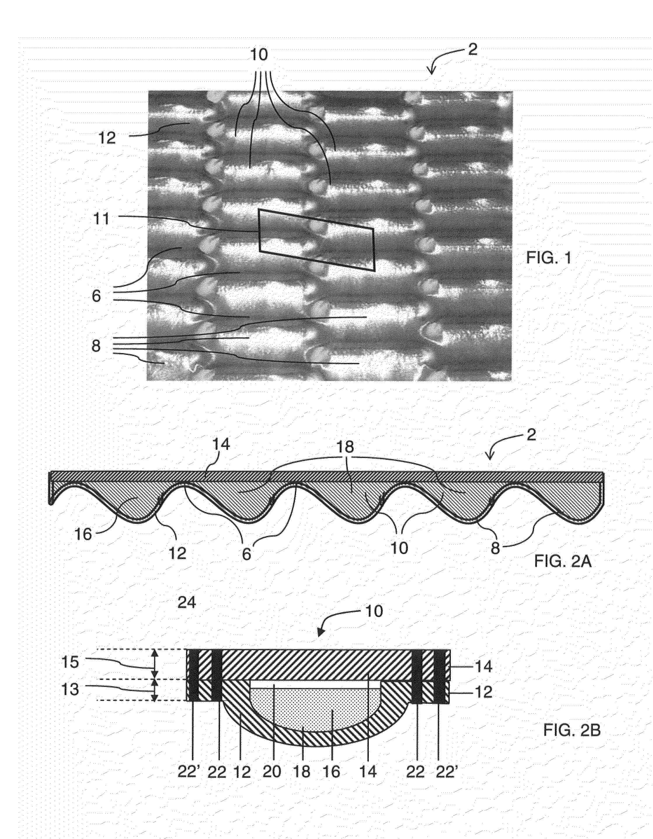
[0143]Example 1 is an article including 7 sealed spaces containing thermal energy storage material and suitable for heat storage. The packs are formed by filling a base sheet having 7 troughs with a thermal energy storage material. Each trough is capable of containing about 7 cm3 of a liquid. The base sheet is covered with a flat cover sheet. The base sheet and the cover sheet are made of stainless steel 304 and have a thickness of about 0.102 mm. The thermal energy storage material is a metal salt and has a liquidus temperature of about 195° C. The thermal energy storage material is anhydrous or has a moisture concentration of about 0.01 wt. % or less. The two sheets are joined while the thermal energy storage material is in a solid state (about 23° C.). A primary seal is provided by laser welding together the base sheet and the cover sheet about the periphery of each sealed space. When heated to a temperature of about 250° C., the sealed space has an internal pressure of about 69 ...


PUM

PropertyMeasurementUnit
temperatureaaaaaaaaaa
pressureaaaaaaaaaa
pressureaaaaaaaaaa

Abstract

The present invention relates to articles and heat storage devices for storage of thermal energy. The articles include a metal base sheet and a metal cover sheet, wherein the metal base sheet and the metal cover sheet are sealingly joined to form one or more sealed spaces. The articles include a thermal energy storage material that is contained within the sealed spaces. The sealed spaces preferably are substantially free of water or includes liquid water at a concentration of about 1 percent by volume or less at a temperature of about 25° C., based on the total volume of the sealed spaces. The articles include one or more of the following features: a) the pressure in a sealed space is about 700 Torr or less, when the temperature of the thermal energy storage material is about 25° C.; b) the metal cover sheet includes one or more stiffening features, wherein the stiffening features include indents into the sealed space, protrusions out of the sealed space, or both, that are sufficient in size and number to reduce the maximum von Mises stress in the cover sheet during thermal cycling; c) the metal cover sheet and / or the metal base sheet includes one or more volume expansion features; or d) the metal cover sheet has a thickness, tc, and the metal base sheet has a thickness, tb, wherein tc is greater than tb; so that the article is durable. For example, the article does not leak after thermal cycling between about 25° C. and about 240° C., for 1,000 cycles.

Description

CLAIM OF BENEFIT OF FILING DATE[0001]The present invention claims the benefit of the filing date of U.S. Provisional Patent Application No. 61 / 373,008, filed on Aug. 12, 2010, the contents of which are hereby incorporated by reference in their entirety.FIELD OF THE INVENTION[0002]The present invention relates to thermal energy storage using a thermal energy storage material and to the packaging of the thermal energy storage material to allow for both efficient heat storage and efficient heat transfer.BACKGROUND OF THE INVENTION[0003]Industry in general has been actively seeking a novel approach to capture and store waste heat efficiently such that it can be utilized at a more opportune time. Further, the desire to achieve .energy storage in a compact space demands the development of novel materials that are capable of storing high energy content per unit weight and unit volume. Areas of potential application of breakthrough technology include transportation, solar energy, industrial...

Claims


Application Information

Patent Timeline
Patent Type & Authority Applications(United States)
IPC IPC(8): F24H7/00B65B1/04B65B31/02
CPCF28D20/02F28F2225/00F28F2265/14F28F2275/06F28D2020/0008Y02E60/145Y02E60/14B65B1/04B65B31/02C09K5/00F24H7/00
Inventor TUDOR, JAY M.SOUKHOJAK, ANDREY N.BANK, DAVID H.SEHANOBISH, KALYANWALIA, PARVINDER S.
Owner DOW GLOBAL TECH LLC
Why Eureka
Try Eureka