Switching power source apparatus

a power source and power supply technology, applied in the direction of electric variable regulation, process and machine control, instruments, etc., can solve the problems of reducing affecting so as to reduce the number of switching operations, improve the efficiency of switching power supply apparatus, and improve the effect of efficiency

Inactive Publication Date: 2012-02-23
SANKEN ELECTRIC CO LTD
View PDF2 Cites 16 Cited by
  • Summary
  • Abstract
  • Description
  • Claims
  • Application Information

AI Technical Summary

Benefits of technology

[0023]In recent years, the switching power source apparatus is required, in view of energy saving, to realize high efficiency in a light load state. To improve efficiency of the switching power source apparatus under light load, a widely used technique is reducing the number of switching operations under light load to minimize a switching loss. This technique becomes one of the essential techniques the switching power source apparatus must employ.
[0024]In consideration of the problems of the related art, the present invention provides a switching power source apparatus capable of improving efficiency under light load, stably operating even with an output capacitor of small ESR, and securing a good load regulation characteristic.
[0025]According to an aspect of the present invention, the switching power source apparatus includes a high-side switch connected to an input voltage, a ramp signal generator configured to generate a ramp signal in synchronization with a switching frequency of the high-side switch, an amplitude signal generator configured to generate an amplitude signal corresponding to an amplitude of the ramp signal, and a controller configured to control the ON timing of the high-side switch according to the ramp signal, a feedback signal, and a first reference voltage and control the ON width of the high-side switch according to the amplitude signal. The ramp signal generator controls, according to the amplitude signal, the inclination of the ramp signal so that the ramp signal maintains a predetermined amplitude. The controller controls the ON width of the high-side switch so that the ON width does not become narrower than a predetermined limit value.

Problems solved by technology

The technique of superposing a ramp signal having a given inclination on the feedback voltage FB or reference voltage REF according to Patent Documents 1 and 2, however, has a problem.
This results in changing the output voltage Vout, to deteriorate a load regulation that is an important characteristic of the DC-DC converter.
However, the smaller the output load current Iout, the longer the ON timing of the high-side MOSFET 11 delays.
This results in deteriorating the load regulation characteristic of the switching power source apparatus.
This means that there is a large voltage difference ΔVL between light load and heavy load, to deteriorate the load regulation characteristic of the switching power source apparatus.

Method used


Image

  • Switching power source apparatus
  • Switching power source apparatus
  • Switching power source apparatus

Examples


embodiment 1

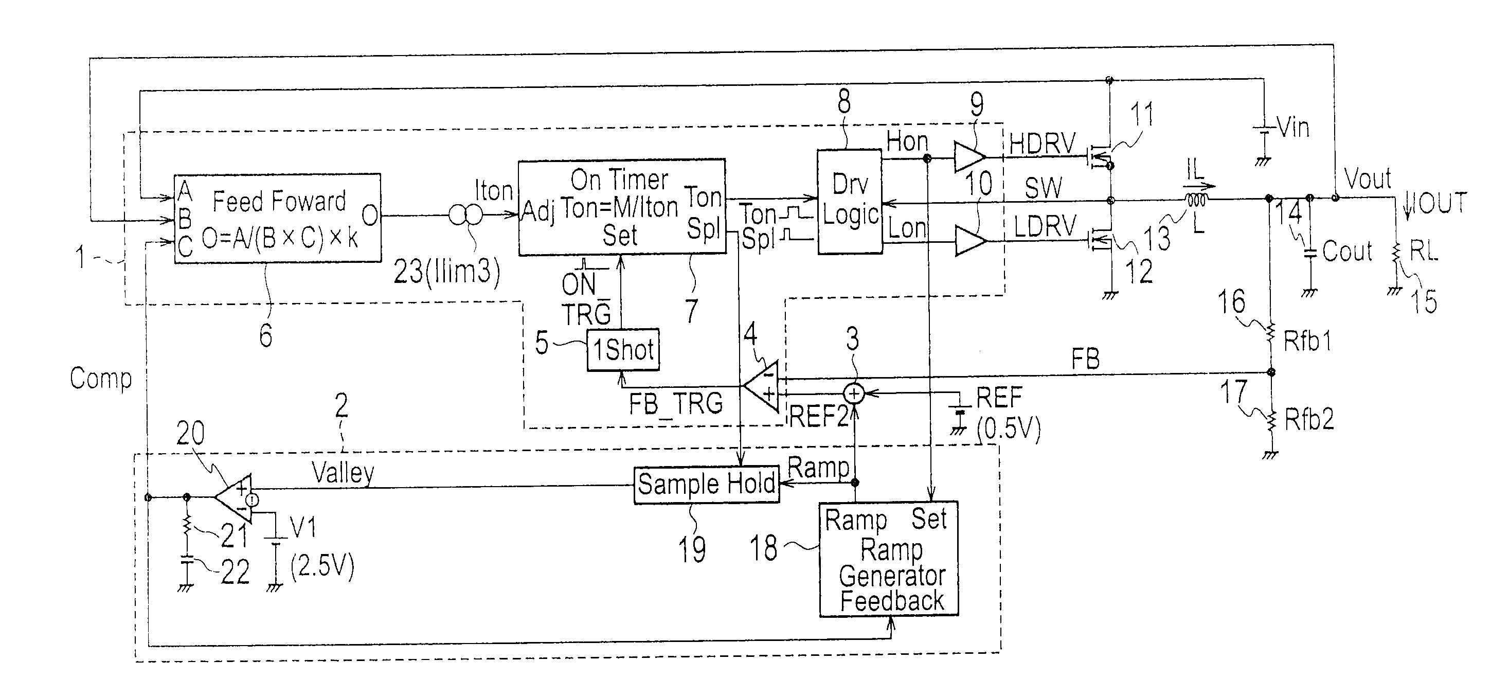
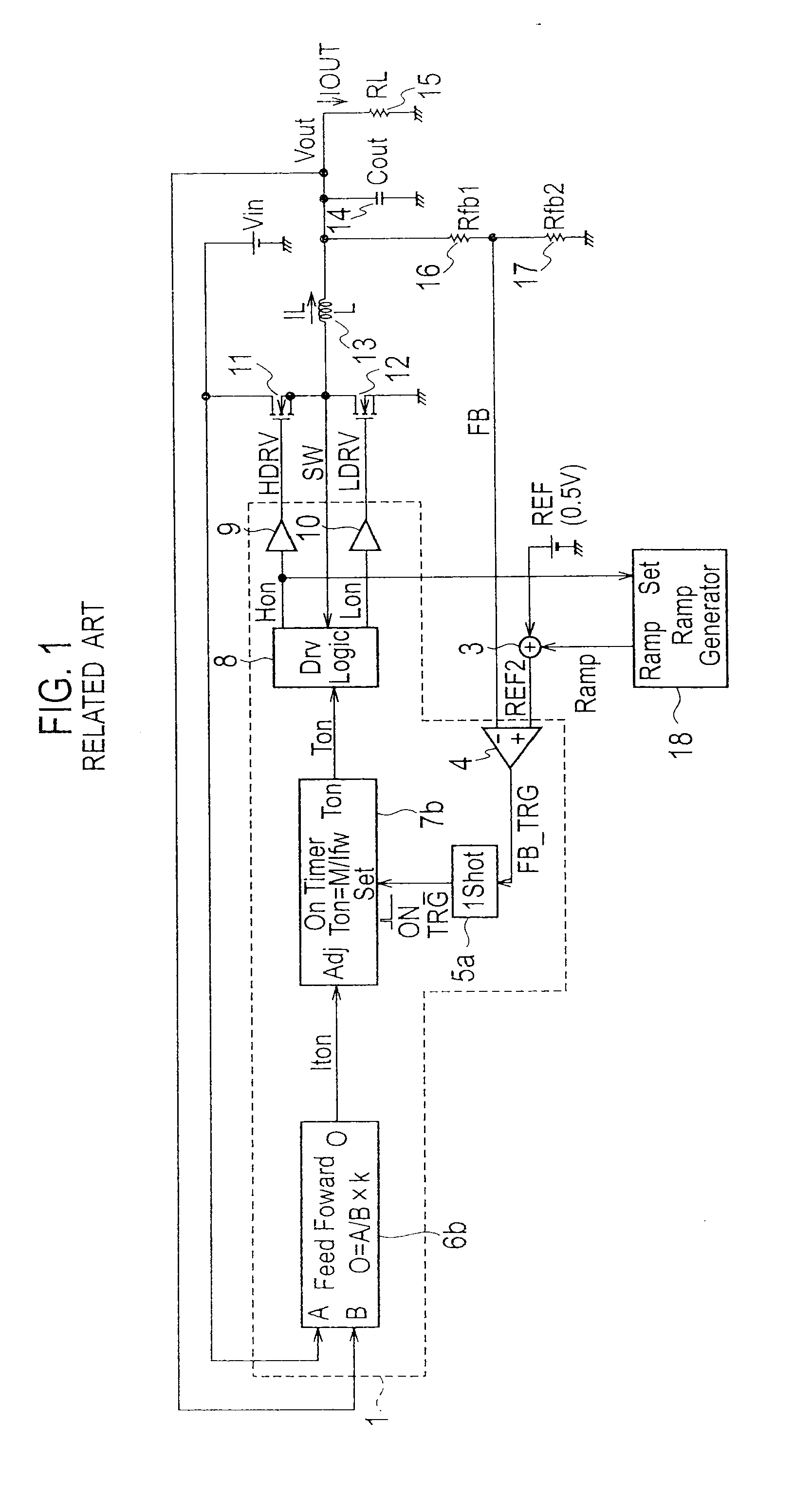
[0043]FIG. 3 is a circuit diagram illustrating a switching power source apparatus according to Embodiment 1 of the present invention. Parts of FIG. 3 that are similar to those of the related art of FIG. 1 are represented with like reference numerals to avoid a repetition of explanation.

[0044]In FIG. 3, the switching power source apparatus according to the present embodiment includes a first feedback controller 1, a second feedback controller 2, a superposing circuit 3, a high-side MOSFET 11, a low-side MOSFET 12, an inductor 13, an output smoothing capacitor 14, an output load 15, and feedback resistors 16 and 17.

[0045]The first feedback controller 1 includes a feedback comparator 4, a one-shot circuit 5, a feedforward circuit 6, an ON timer 7, a drive logic 8, a high-side driver 9, a low-side driver 10, and a current limiter 23.

[0046]The second feedback controller 2 includes a ramp generator 18, a sample and hold circuit 19, an error amplifier 20, a phase compensation resistor 21, ...

embodiment 2

[0111]FIG. 15 is a circuit diagram illustrating a switching power source apparatus according to Embodiment 2 of the present invention. Embodiment 2 differs from Embodiment 1 of FIG. 3 in that Embodiment 2 employs a superposing circuit 3b whose configuration and connected location are different from those of the superposing circuit 3 of Embodiment 1. Except this, Embodiment 2 is the same as Embodiment 1, and therefore, the same reference marks as those of Embodiment 1 are used for Embodiment 2, to omit a repetition of explanation.

[0112]The superposing circuit 3b corresponds to the second superposing circuit stipulated in the claims. The superposing circuit 3b generates a third ramp signal having a negative inclination corresponding to the amplitude and frequency of the ramp signal Ramp generated by the ramp generator 18 and superposes the third ramp signal on the feedback signal FB, to generate a second superposed signal FB2.

[0113]FIG. 16 is a circuit diagram illustrating the details...


PUM


Abstract

A switching power source apparatus includes a high-side MOSFET 11, a ramp generator 18 to generate a ramp signal, an amplitude signal generator (second feedback controller 2) to generate an amplitude signal Comp corresponding to an amplitude of the ramp signal, and a first feedback controller 1 to control the ON timing of the high-side MOSFET 11 according to the ramp signal, a feedback signal FB, and a first reference voltage REF and control the ON width of the high-side MOSFET 11 according to the amplitude signal Comp. The ramp generator 18 controls the inclination of the ramp signal so that the ramp signal maintains a predetermined amplitude. The first feedback controller 1 controls the ON width of the high-side MOSFET 11 so that the ON width does not become narrower than a predetermined limit value.

Description

BACKGROUND OF THE INVENTION[0001]1. Field of the Invention[0002]The present invention relates to a switching power source apparatus for supplying a stable DC voltage.[0003]2. Description of Related Art[0004]A DC-DC converter for supplying a source voltage to a digital signal processing LSI such as an image engine or a CPU is required to have an improved load response to minimize variation in an output voltage when the LSI dynamically changes its load. To meet the requirement, some DC-DC converter employs an error amplifier to compare an output voltage with a reference voltage. The error amplifier, however, causes a delay that may deteriorate the load response of the DC-DC converter. To avoid the delay caused by the error amplifier, a device that is widely used is a ripple converter employing no error amplifier, and instead, adopting PFM (pulse frequency modulation) control to improve load response with respect to a load variation in the digital device.[0005]A PFM ripple converter ac...

Claims


Application Information

Patent Timeline
Patent Type & Authority Applications(United States)
IPC IPC(8): G05F1/10
CPCH02M3/1588Y02B70/1466H02M2001/0025Y02B70/10H02M1/0025H02M3/28
Inventor NAKAMURA, MASARU
Owner SANKEN ELECTRIC CO LTD
Why Eureka
Try Eureka