Electrolytic solution for electric double layer capacitor, electric double layer capacitor using the same, and manufacturing method therefor

a manufacturing method and technology applied in capacitors, hybrid capacitor electrolytes, capacitors/absorbents, etc., can solve the problems of poor heat resistance of emc and dmc, unstable quality of electric double layer capacitors, and high vapor pressure or bumping, etc., to achieve stable quality

Inactive Publication Date: 2012-02-23
SEIKO INSTR INC
View PDF20 Cites 15 Cited by
  • Summary
  • Abstract
  • Description
  • Claims
  • Application Information

AI Technical Summary

Benefits of technology

[0011]In addition, the electric double layer capacitor is often used continuously under the application of a voltage of 2.0 V or more or a high voltage of 3.0 V or more from a main power source. When a high voltage is applied to the electrolytic solution, the degradation of a solute or solvent of the electrolytic solution is accelerated and facilitates a decrease in function of the electrolytic solution. In particular, when an ambient temperature at which the voltage is applied is high, a significant decrease in function occurs. Therefore, the high-voltage applicable electric double layer capacitor requires an increasing amount of the electrolytic solution. However, an increasing amount of the electrolytic solution may facilitate a leakage of the electrolytic solution when the lid and the container body are joined by welding or reflow soldering. As a result, the quality of the electric double layer capacitor may become unstable.
[0019]According to the present invention, the electric double layer capacitor having stable quality can be obtained.

Problems solved by technology

EMC and DMC have poor heat resistance because of comparatively low boiling points (less than 200° C.).
Thus, EMC and DMC are easily vaporized to cause high vapor pressure or bumping when the lid and the container body of the electric double layer capacitor of a chip type are joined together.
For example, the remaining amount of an electrolytic solution may vary widely and the quality, such as service capacity, of the electric double layer capacitor may be unstable.
In addition, as the solvent has a low boiling point, an increase in vapor pressure of the electrolytic solution leads to an increase in internal pressure when the lid and the container body are welded together.
As a result, the housing container may be damaged.
As the electric double layer capacitor is heated at about 240 to 260° C. by reflow soldering, an increase in vapor pressure may make the sealed portion weak.
Thus, the leakage of the electrolytic solution may occur and the quality of the electric double layer capacitor may become unstable.
In particular, when an ambient temperature at which the voltage is applied is high, a significant decrease in function occurs.
However, an increasing amount of the electrolytic solution may facilitate a leakage of the electrolytic solution when the lid and the container body are joined by welding or reflow soldering.
As a result, the quality of the electric double layer capacitor may become unstable.

Method used


Image

  • Electrolytic solution for electric double layer capacitor, electric double layer capacitor using the same, and manufacturing method therefor
  • Electrolytic solution for electric double layer capacitor, electric double layer capacitor using the same, and manufacturing method therefor
  • Electrolytic solution for electric double layer capacitor, electric double layer capacitor using the same, and manufacturing method therefor

Examples


example 1-1

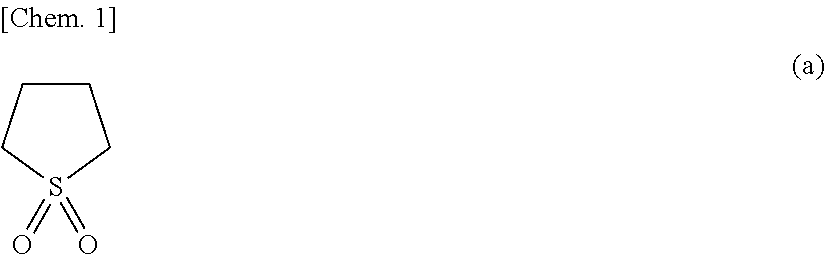
[0134]An electrolytic solution was prepared by mixing sulfolane (in the table, represented by SL) and dimethyl sulfone (in the table, represented by DMS) at a ratio of SL:DMS=8:2 (mass ratio) to prepare a nonaqueous solvent, and dissolving the SBP-BF4 as an electrolytic electrolyte in the nonaqueous solvent so as to have a concentration of 1.5 mol / dm3.

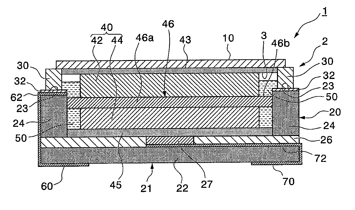
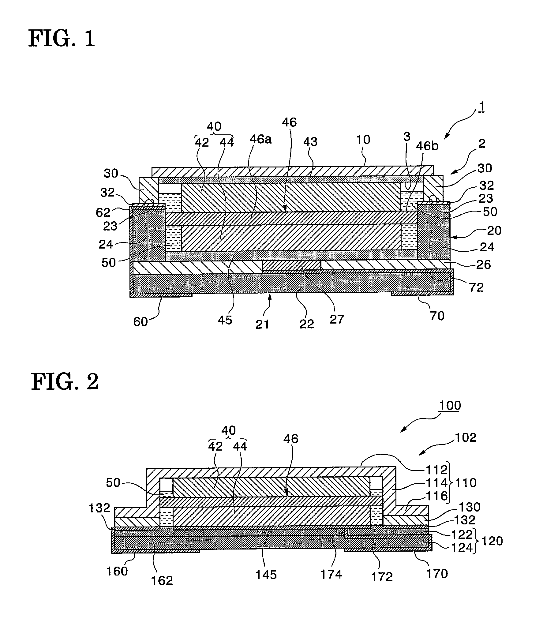
[0135]By using the resulting electrolytic solution, an electric double layer capacitor similar to that shown in FIG. 1 was prepared as described below.

[0136]Commercial active carbon (specific surface area: 1,900 m2 / g, pore volume: 0.85 cm3 / g, fine pore ratio: 4%, medium-sized pore ratio: 95%, and number average pore size: 12 μm (measured by a laser mode)) was extended into a sheet of 0.25 mm±0.05 mm in thickness by applying pressure and then cut into pieces each having a size of 1.7 mm×1.0 mm. The resulting pieces are used as a cathode side electrode and an anode side electrode. The anode side electrode was attached to a lid, which was...

example 1-2

[0141]An electric double layer capacitor was obtained in the same manner as in that of Example 1-1, except that the nonaqueous solvent used was sulfolane:ethylmethyl sulfone (EMS)=8:2 (mass ratio). Then, the low-temperature capacity retention rate was obtained.

example 2-1

[0145]An electric double layer capacitor was obtained in the same manner as in Example 1-2, except that the concentration of SBP-BF4 was 1.0 mol / dm3. Ten electric double layer capacitors thus obtained were applied with a voltage of 3.3 V at an ambient temperature of 70° C. and then stored at 60° C. for 20 days. Subsequently, at an ambient temperature of 24° C., the electric double layer capacitor after the storage was discharged at a constant current of 5μA (discharge current) until the voltage reached 2.0 V. Then, the service capacity was calculated and the average value was defined as a high-temperature capacity. The high-temperature capacity thus obtained and the initial capacity obtained separately were substituted into the following equation (III) to calculate a high-temperature capacity retention rate.

High-temperature capacity retention rate(%)=high-temperature capacity / initial capacity×100  (III)


PUM


Abstract

Provided are an electrolytic solution for an electric double layer capacitor capable of providing an electric double layer capacitor having stable quality, an electric double layer capacitor using the electrolytic solution, and a manufacturing method for the electric double layer capacitor. The electrolytic solution includes a supporting electrolyte, sulfolane, and a linear sulfone. It is preferred that the electrolytic solution further include an organic fluorine compound. Further, it is preferred that the supporting electrolyte contain 5-azoniaspiro[4.4]nonane tetrafluoroborate, and the content of 5-azoniaspiro[4.4]nonane tetrafluoroborate be 1.5 to 3.6 mol / dm3.

Description

RELATED APPLICATIONS[0001]This application claims priority under 35 U.S.C. §119 to Japanese Patent Application Nos. 2010-183198 filed on Aug. 18, 2010 and 2011-137328 filed on Jun. 21, 2011, the entire contents of which are hereby incorporated by reference.BACKGROUND OF THE INVENTION[0002]1. Field of the Invention[0003]The present invention relates to an electrolytic solution for an electric double layer capacitor, an electric double layer capacitor using the electrolytic solution, and a manufacturing method for the electric double layer capacitor.[0004]2. Description of the Related Art[0005]An electric double layer capacitor includes a pair of polarizable electrodes, a separator interposed between the pair of polarizable electrodes, and an electrolytic solution, with which the pair of polarizable electrodes and the separator are impregnated, in a housing container sealed with a lid and a container body. In various small-sized electronic devices, such as mobile phones, PDAs, and por...

Claims


Application Information

Patent Timeline
Patent Type & Authority Applications(United States)
IPC IPC(8): H01G9/155H01G9/022H01G9/00H01G11/22H01G11/28H01G11/30H01G11/42H01G11/54H01G11/60H01G11/62H01G11/86
CPCY02E60/13H01G11/58H01G11/26
Inventor HOMMO, TOMOHIROSATO, ROYOIKAWA, TOMOKOTAMACHI, TSUNEAKISHINODA, ISAMUWATANABE, SUNJI
Owner SEIKO INSTR INC
Why Eureka
Try Eureka