Foamed polyvinylidene fluoride structure

a polyvinylidene fluoride and polyvinylidene technology, applied in the field of foamed fluoropolymer, can solve the problems of poor melt strength, limited foaming of pvdf, and high density of pvdf, and achieves the effects of reducing the density of pvdf, reducing the foaming rate, and improving the foaming ra

Inactive Publication Date: 2012-02-23
ARKEMA INC
View PDF3 Cites 55 Cited by
  • Summary
  • Abstract
  • Description
  • Claims
  • Application Information

AI Technical Summary

Benefits of technology

[0012]b) 0.01 to 5 percent by weight of residual nucleating agent; (0.1-2) wherein said foamed structure has a density that is at least 3% less than said fluoropolymer of a) that is unfoamed; wherein said structure has been sized; and

Problems solved by technology

Unfortunately PVDF has a relatively high density, and can be more expensive than other more commodity polymer resins.
Unfortunately, poor melt strength and difficulty in controlling the cell formation in the molten state has generally limited the foaming of PVDF to either a batch process, foaming with support, or some exotic process such as latex freezing.
It is impossible to make hollow or long articles, such as pipes, with solid skins using this method.
The foam extruded in this case would not be able to hold its own without the support of a carrier, especially in large size applications.
Therefore, it is not possible to size the product or create a hollow freestanding profile.
As the result, this technology is only limited to making PVDF wire coating.
Unfortunately this compromises the advantageous properties of the PVDF foam, especially those related to high crystallinity.
This process is not useful for producing hollow or long and thin articles with solid skins.

Method used


Image

  • Foamed polyvinylidene fluoride structure
  • Foamed polyvinylidene fluoride structure

Examples


example 1

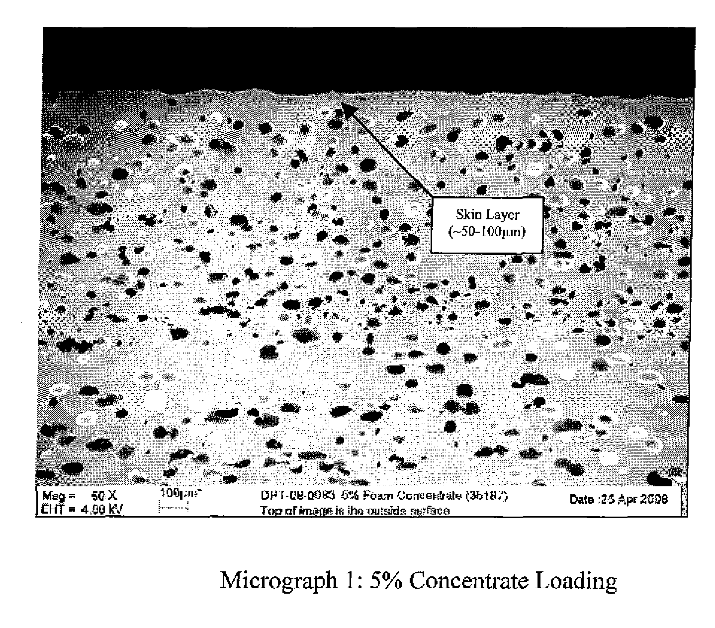
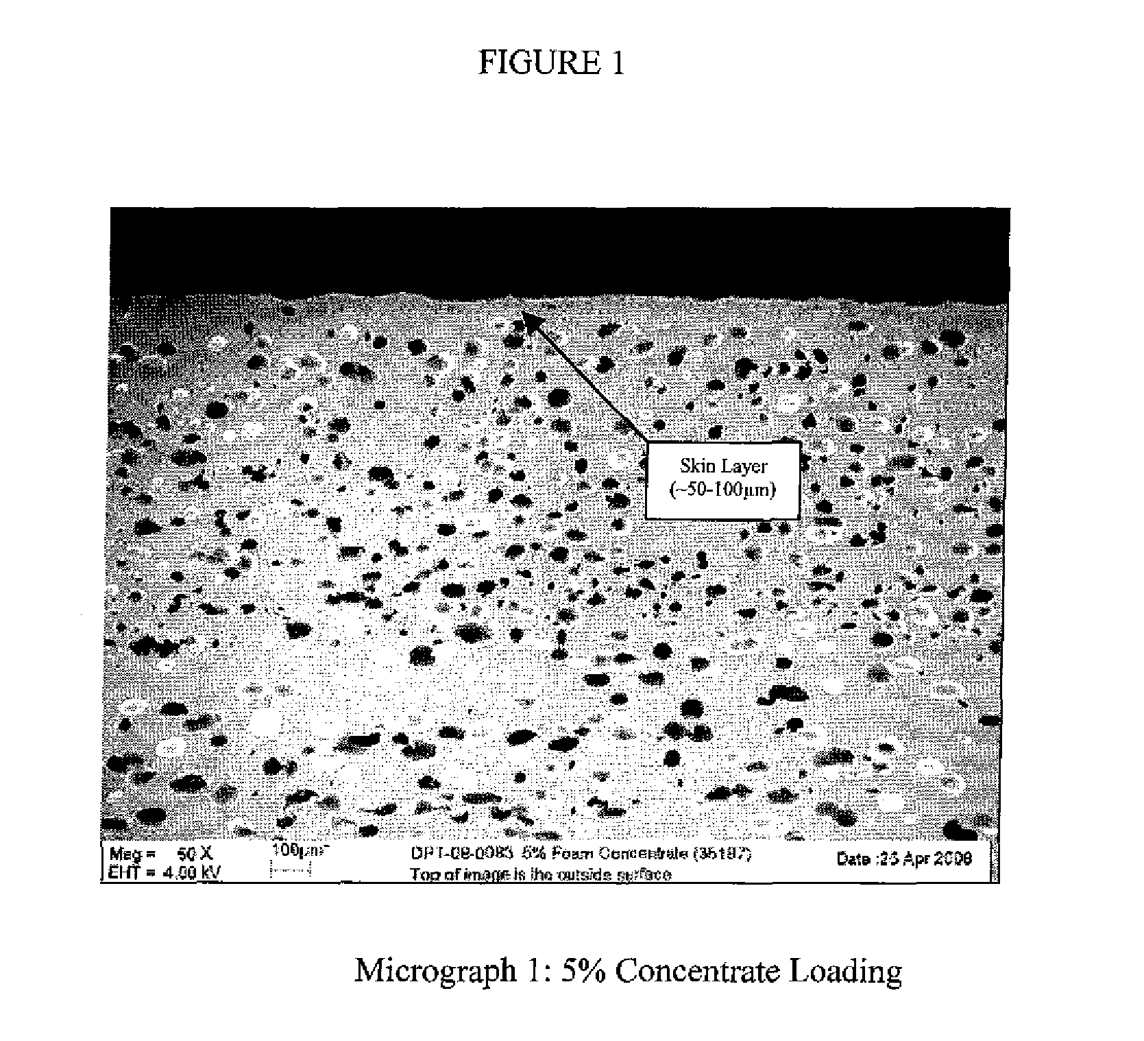
[0072]A ⅜″ KYNAR PVDF foam tube with a density of 1.213 g / cc, which is a weight reduction of 32%, was created using the following procedure.

[0073]A mixture of 5% master batch of concentrate that consists of 10% small azodicarbonamide chemical foaming agent, 1% nucleating agent with a surface area of 22 m2 / g, and 89% KYNAR 2821 base resin, which has a melting point of 140-145° C. and melt viscosity of 12.0-20.0 Kpoise, and 95% KYNAR 2800, which has a melting point of 140-145° C. and melt viscosity of 23.0-27.0 Kpoise, was prepared.

[0074]The screw is a 1.5″ diameter general purpose metering screw with a 3:1 compression having a L / D of 26:1.

[0075]The pin and die was attached to a two-leg spider die, with a port to allow airflow through the spider leg into the center of the tube. To make ⅜″ tubing with a 0.040″ wall thickness a die of 0.397″ inside diameter and a pin of 0.306″ outside diameter was selected. This pin and die will produce a draw balance of 1.021 and a draw down ratio of 1...

example 2

[0077]KYNAR PVDF foam ⅜″ tubes were extruded with 0.040″ wall by adding 10% master batch with and without nucleating agents to KYNAR 2800 base resin, which has a melting point of 140-145° C. and melt viscosity of 23.0-27.0 Kpoise. The nucleating agent master batch was CaCO3 with surface area of 22 m2 / g. The chemical foaming agent in the master batch was large particle size azodicarbonamide. The master batch without nucleating agent had 10% chemical foaming agent and 90% KYNAR 2821, which has a melting point of 140-145° C. and melt viscosity of 12.0-20.0 Kpoise. The master batch with the nucleating agent had 1% CaCO3, 10% chemical foaming agent and 89% KYNAR 2821-10. The materials were processed in a 1.5″ single screw extruder with the following process conditions (Table 2)

TABLE 2HeadLineWaterExt.BarrelBarrelBarrelBarrelDie 1Die 2Die 3Press.LoadSpeedTempSpeed1 (° F.)2 (° F.)3 (° F.)4 (° F.)(° F.)(° F.)(° F.)(psi)(%)(ft / min)(° F.)(RPM)3153553804053303153151700569.69010.3

The study show...

example 3

[0078]A ⅜″ tube with 0.035″ wall thickness was made using 10% p-toluenesulfonylsemicarbazide chemical foaming agent master batch from ROWA Group USA and 90% KYNAR 2800-00, which has a melting point of 140-145° C. and melt viscosity of 23.0-27.0 Kpoise. The materials were processed in a 1.5″ single screw extruder at the following processing extruder conditions as shown in Table 3.

TABLE 3LineWaterExt.Barrel 1Barrel 2Barrel 3DieSpeedTempSpeed(° F.)(° F.)(° F.)(° F.)(ft / min)(° F.)(RPM)3553754003408909-13

The barrel zone 4 temperatures were varied. The following properties (Table 4) were observed for the varied temperatures.

TABLE 4Barrel 4Density% Weight° F.(g / cc)ReductionSurface Finish4350.90450%Rough4151.38223%Smooth4051.52415%Very Smooth


PUM

PropertyMeasurementUnit
thickaaaaaaaaaa
weight percentaaaaaaaaaa

Abstract

The invention relates to a foamed fluoropolymer, preferably a polyvinylidene fluoride (PVDF) structure, such as from Kynar® resins. The foamed structure is continuous self-supporting, sized, and has a dense skin. The foamed structure is manufactured in a process using foaming agents and nucleating agents. The structure is sized into a specific shape during the manufacturing process—requiring a good melt viscosity of the PVDF foam. In one process, a master batch containing the nucleating agent is used. The foamed article could be a sheet, film, profile, tube, pipe, article, rod foam-core structure, or other self-supporting shape. Foamed tubes, pipes, rods, sheets and conduit are especially useful. The foamed structure of the invention provides added value by being lighter weight, more flexible, and more impact resistant than a comparable non-foamed PVDF structure. It also has increased hysteresis, increased insulation properties, reduced dielectric constant, and increased compressibility.

Description

FIELD OF THE INVENTION[0001]The invention relates to a foamed fluoropolymer, preferably a polyvinylidene fluoride (PVDF), structure that is self-supporting, sized, and has a dense skin. The foamed structure is manufactured in a process using foaming agents and nucleating agents. The structure is sized into a specific shape during the manufacturing process—requiring a good melt viscosity of the PVDF foam. In one process, a master batch containing the nucleating agent is used. The foamed article could be a sheet, film, profile, tube, pipe, or other self-supporting shape or article. Foamed tubes, pipes and conduit are especially useful.BACKGROUND OF THE INVENTION[0002]Fluoropolymers, and polyvinylidene fluoride in particular, possess many favorable physical properties that make them the material of choice in many applications. Polyvinylidene fluoride (PVDF) has a marked toughness and high elasticity, and has a high chemical, weathering, permeation and flammability resistance. It is wid...

Claims


Application Information

Patent Timeline
Patent Type & Authority Applications(United States)
IPC IPC(8): C08J9/34C08K3/34C08K3/30C08K3/04C08J9/06C08L27/16C08L27/20C08L27/18C08K3/22B32B1/08C08K3/26C08K5/098
CPCC08J9/12C08J2201/03Y10T428/1393C08J9/0066C08J2327/16
Inventor ZERAFATI, SAEIDSTABIER, SEAN M.
Owner ARKEMA INC
Why Eureka
Try Eureka