Semiconductor die terminal

a technology of semiconductor devices and die terminals, which is applied in the direction of semiconductor devices, semiconductor/solid-state device details, electrical apparatus, etc., can solve the problems of device not being connected size and distance between die terminals being so small, and the device not being able to connect to the final pcb

Inactive Publication Date: 2012-03-01
HSIO TECH
View PDF15 Cites 56 Cited by
  • Summary
  • Abstract
  • Description
  • Claims
  • Application Information

AI Technical Summary

Benefits of technology

[0010]The present disclosure relates to the use of additive printing processes to create semiconductor die terminals, typically

Problems solved by technology

In many cases, the size and distance between die terminals is so small that the device cannot be connected to the final PCB without some sort of fan out or routing.
In many cases, the size and distance between die terminals is so small that the IC device cannot be connected to the final PCB without some sort of re-routing interface.
The main limitation of the process is the plating process that is used to grow the copper terminals.
In both cases, the connection of the IC device to the package is generally not reworkable once packaged and if there is

Method used


Image

  • Semiconductor die terminal
  • Semiconductor die terminal
  • Semiconductor die terminal

Examples


Embodiment Construction

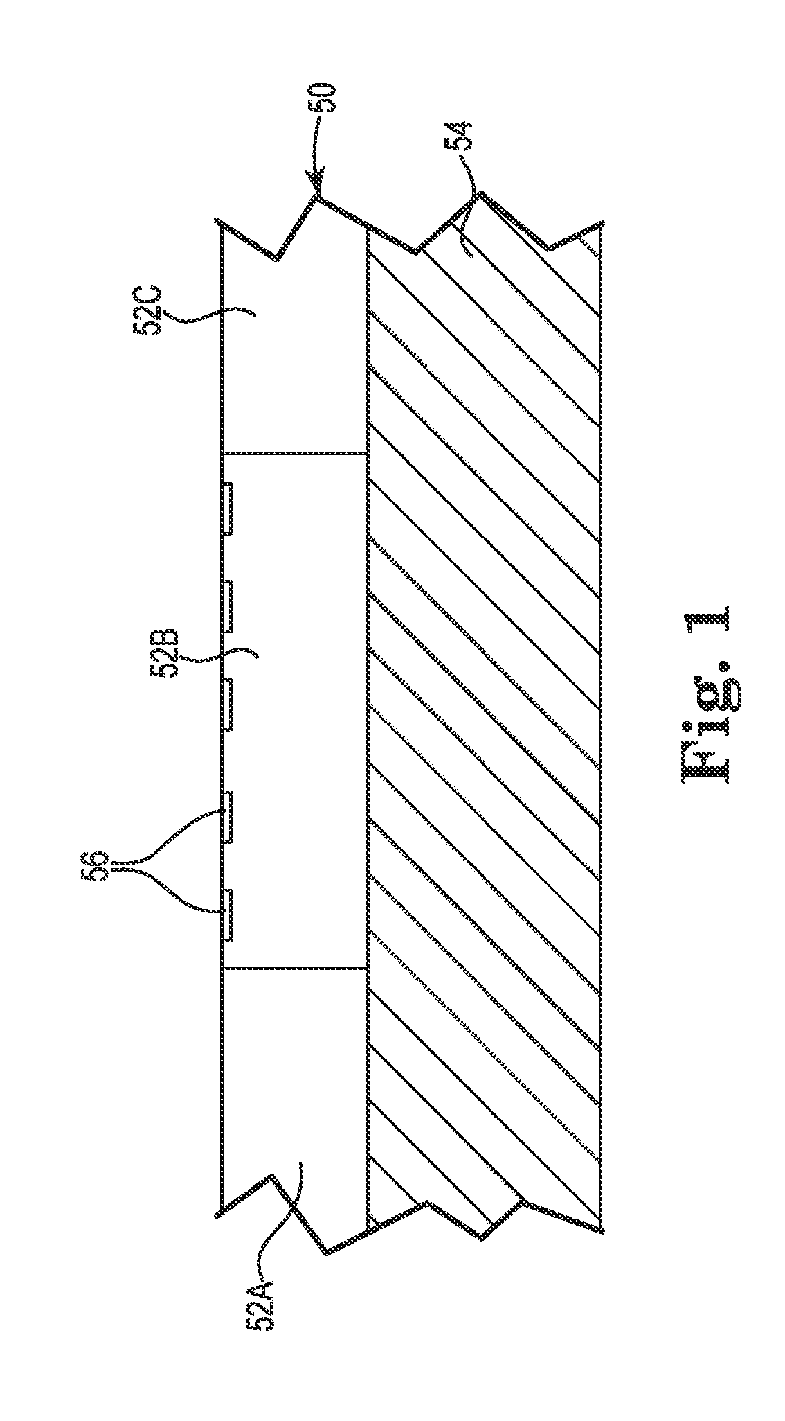
[0033]FIG. 1 is a side sectional view of semiconductor wafer 50 containing a plurality of IC devices 52A, 52B, 52C (collectively “52”) located on substrate 54. The IC terminals 56 are facing up. The substrate 54 may be a temporary work surface or may be a portion of a semiconductor package.

[0034]The substrate 54 can be constructed from a variety of rigid or flexible polymeric materials, such as for example, UV stabilized tetrafunctional epoxy resin systems referred to as Flame Retardant 4 (FR-4); bismaleimide-triazine thermoset epoxy resins referred to as BT-Epoxy or BT Resin; and liquid crystal polymers (LCPs), which are polyester polymers that are extremely unreactive, inert and resistant to fire. Other suitable plastics include phenolics, polyester (PET), polyimide (PI), polyethylene napthalate (PEN), Polyetherimide (PEI), along with various fluoropolymers (FEP) and copolymers, and Ryton® available from Phillips Petroleum Company. For some applications, the substrate 54 can be a ...


PUM


Abstract

A method of making semiconductor die terminals and a semiconductor device with die terminals made according to the present method. At least a first mask layer is selectively printed on at least a portion of a wafer containing a plurality of the semiconductor devices to create first recesses aligned with electrical terminals on the semiconductor devices. A conductive material is deposited in a plurality of the first recesses to form die terminals on the semiconductor devices. The first mask layer is removed to expose the die terminals, and the wafer is diced into a plurality of discrete semiconductor devices.

Description

TECHNICAL FIELD[0001]The present application is directed to leveraging the capabilities of additive printing processes to provide semiconductor die terminals that results in a high performance packaged IC devices after wafer dicing.BACKGROUND OF THE INVENTION[0002]Traditional semiconductors and IC devices are typically packaged in a variety of ways to provide redistribution from the terminals on the die to a spacing that is conducive to cost effective printed circuit board (“PCB”) fabrication techniques. In many cases, the size and distance between die terminals is so small that the device cannot be connected to the final PCB without some sort of fan out or routing. The packages also serve to protect the fragile silicon or provide additional functions such as thermal management or near device decoupling. In many cases, the size and distance between die terminals is so small that the IC device cannot be connected to the final PCB without some sort of re-routing interface.[0003]Most I...

Claims


Application Information

Patent Timeline
IPC IPC(8): H01L23/48H01L21/78
CPCH01L21/6836H01L23/3107H01L2924/1306H01L2924/0001H01L2224/13147H01L2224/11902H01L2924/014H01L24/11H01L24/13H01L24/94H01L2221/68327H01L2224/11002H01L2224/1147H01L2224/11505H01L2224/11901H01L2224/13099H01L2924/01004H01L2924/01013H01L2924/01029H01L2924/01046H01L2924/01047H01L2924/01049H01L2924/01078H01L2924/01079H01L2924/01082H01L2924/09701H01L2924/19041H01L2924/3011H01L2924/3025H01L2924/01006H01L2924/01033H01L2924/01075H01L2924/01087H01L2924/00015H01L2924/00H01L2224/0554H01L2224/0557H01L2224/05571H01L2224/05573H01L2224/056H01L2924/00014H01L2924/14H01L2224/05599H01L2224/0555H01L2224/0556
Inventor RATHBURN, JAMES
Owner HSIO TECH
Why Eureka
Try Eureka