Thermal imaging method and appratus for evaluating coatings

a technology of thermal imaging and coatings, applied in the field of thermal imaging methods and appratus for evaluating coatings, can solve the problems of complex computationally, inability or inability to achieve, and limited methods,

Inactive Publication Date: 2012-03-01
GENERAL ELECTRIC CO
View PDF27 Cites 30 Cited by
  • Summary
  • Abstract
  • Description
  • Claims
  • Application Information

AI Technical Summary

Benefits of technology

[0007]According to one aspect of the present invention, an apparatus is provided for determining variable thickness of a coating disposed on a substrate. The apparatus comprises a flash-lamp source capable of generating a thermal pulse at the coating surface, an optical trigger coupled to the flash-lamp source and capable of initiating the flash-lamp firing, a transistor coupled to the flash lamp source and capable of quenching the thermal pulse, and a reflective filter positioned between the flash-lamp source and the coating surface capable of preventing residual heat from the flash-lamp from heating the coating surface. The apparatus also comprise an IR image capture to capture sequential image frames of the coating surface, whereas each sequential image frame corresponds to an elapsed time and comprises a pixel array, and wherein each pixel of the array corresponds to a location on the coating surface, and a processor for controlling the operations of the lamp, receiving the image frames of the coating surface at the initiation of the flash-lamp firing and sequentially there after, and for calculating the thickness of the coating at various points along the substrate using the data received.

Problems solved by technology

Unfortunately, these techniques either include point-by-point measurement of the coating thickness, and therefore take time and are complex computationally or require the presence of a coating thickness standard in the image, which may not be possible or is unfeasible.
However, the method is limited as the calculation is done at a specific point along the surface of the coated part.
The ability to analyze variations in the coating thickness along a large surface area or geometrically complex parts is limited.

Method used


Image

  • Thermal imaging method and appratus for evaluating coatings
  • Thermal imaging method and appratus for evaluating coatings
  • Thermal imaging method and appratus for evaluating coatings

Examples


Embodiment Construction

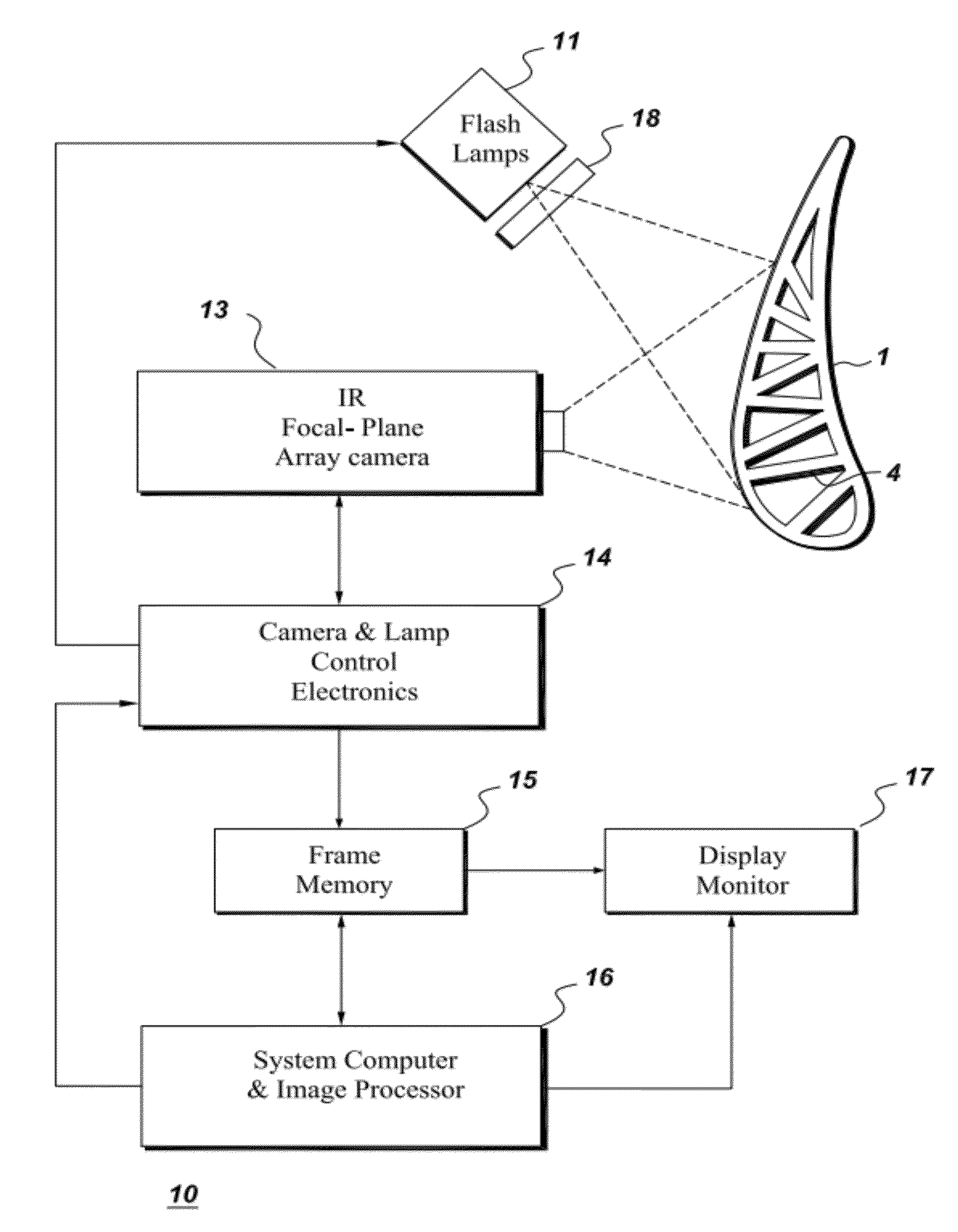
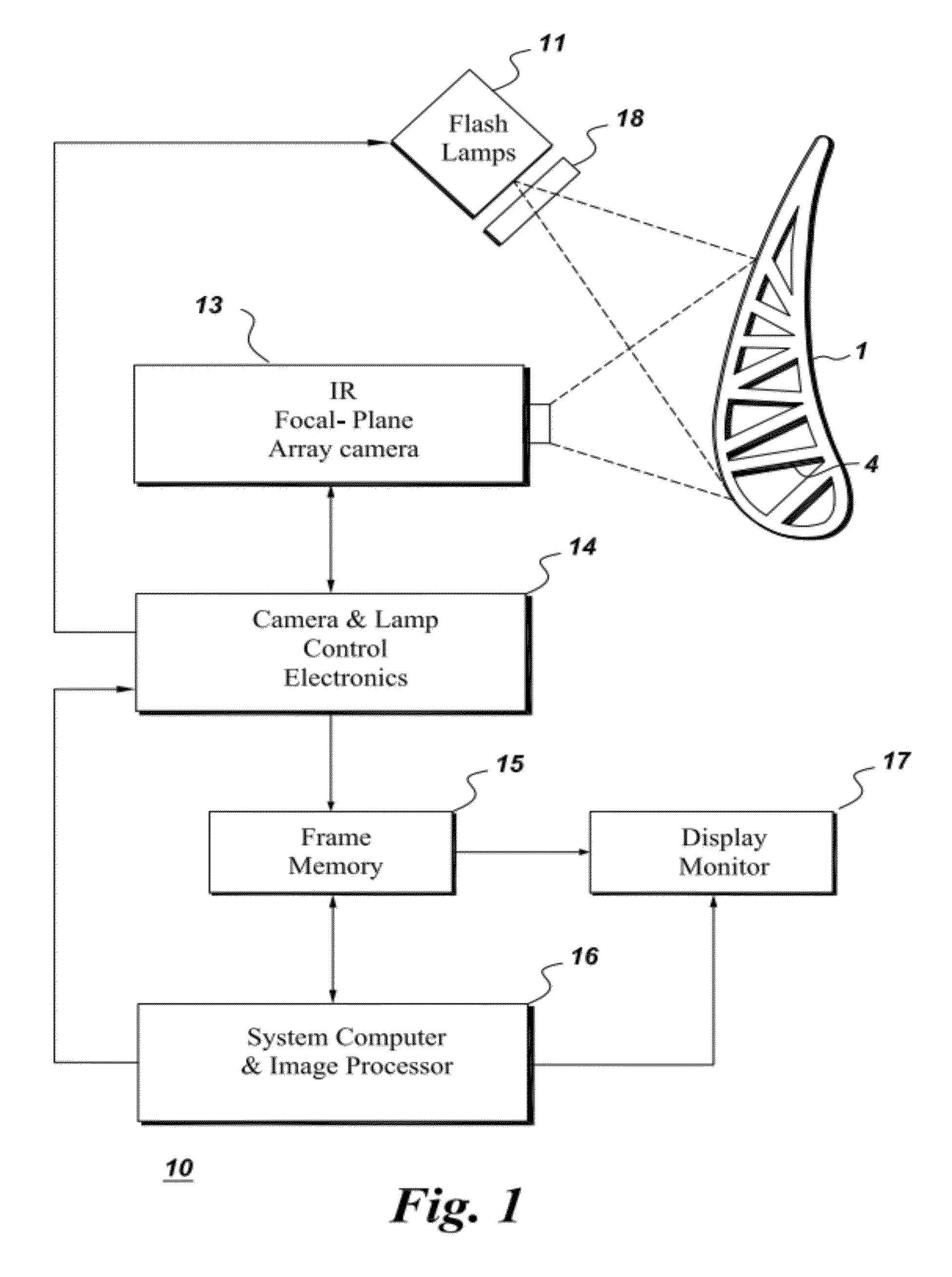
[0015]By way of example, the present invention relates to nondestructive testing methods and apparatus for determining and displaying the actual thickness and the thermal conductivity value of a coating along the surface an object through the use of high-speed infrared (IR) transient thermography. The temporal response of the surface temperature following an optical surface flash and consequent heat pulse generation is analyzed and the coating thickness extracted. A by-product is the coating thermal conductivity.

[0016]FIG. 1 is a diagrammatic representation of an apparatus 10 for determining coating thickness and thermal conductivity for an object 1. More specifically, the exemplary apparatus of FIG. 1 can be used to determine the thickness and thermal conductivity of a coating 4 disposed on a surface of the object using transient IR thermography. The object may be a fabricated part including, but not limited to an aircraft or turbine part. In certain embodiments, the fabricated par...


PUM


Abstract

An apparatus is provided for determining variable thickness of a coating on a surface of a substrate using in part a flash-lamp source, capable of generating a thermal pulse at the coating surface, and a image capture and processing device capable of capture sequential image frames of the coating surface, whereas each sequential image frame corresponds to an elapsed time and comprises a pixel array, and wherein each pixel of the array corresponds to a location on the coating surface. A method of calculating coating thickness is also provided.

Description

BACKGROUND[0001]The present invention in accordance with certain embodiments, relates to thermographic nondestructive testing techniques for determining the thickness of a coating on the surface of an object[0002]In general, infrared (IR) transient thermography is a versatile nondestructive testing technique that relies upon temporal measurements of heat transference through an object to provide information concerning the structure and integrity of the object. Heat flow through an object is substantially unaffected by the microstructure and the single-crystal orientations of the material of the object, therefore, an infrared transient thermography analysis is essentially free of the limitations this creates for ultrasonic measurements. Additionally, transient thermographic analysis approach is not significantly hampered by the size, contour or shape of the object being tested and, moreover, can be accomplished ten to one-hundred times faster than most conventional ultrasonic methods...

Claims


Application Information

Patent Timeline
Patent Type & Authority Applications(United States)
IPC IPC(8): H04N5/33G06F15/00G01J5/00G01B11/06
CPCG01B21/085G01B11/0658G01J5/0896G01J5/0088G01J5/48
Inventor RINGERMACHER, HARRY ISRAELHOWARD, DONALD ROBERTKNIGHT, BRYON EDWARD
Owner GENERAL ELECTRIC CO
Why Eureka
Try Eureka