Grid for radiography and manufacturing method thereof, and radiation imaging system

a radiography and grid technology, applied in imaging devices, instruments, nuclear engineering, etc., can solve the problems of reducing throughput, increasing manufacturing costs, and difficult to embed gold pastes having a high viscosity, and achieves improved radiation absorption. , the effect of easy formation of the seed layer

Inactive Publication Date: 2012-03-01
FUJIFILM CORP
View PDF3 Cites 8 Cited by
  • Summary
  • Abstract
  • Description
  • Claims
  • Application Information

AI Technical Summary

Benefits of technology

[0015]According to the grid of the present invention, the radiation absorbing portion includes the first layer made of the metal colloidal particles having low stress. Thus, the grid is flexible and resistant to external force. The radiation absorbing portions may be provided in the grooves formed in the substrate, or may be provided on the substrate. Use of the gold colloidal particles as the metal colloidal particles allows for improved radiation absorptivity.
[0016]According to the manufacturing method of the grid of the present invention, the seed layer for electrolytic plating is formed by charging the metal colloidal solution into the groove. Thus, it is possible to easily form the seed layer at low cos...

Problems solved by technology

This contrivance or step causes increase in manufacturing costs and reduction in throughput.
Therefore, it is difficult to embed the gold paste having a high viscosity in the minute grooves ha...

Method used


Image

  • Grid for radiography and manufacturing method thereof, and radiation imaging system
  • Grid for radiography and manufacturing method thereof, and radiation imaging system
  • Grid for radiography and manufacturing method thereof, and radiation imaging system

Examples


Embodiment Construction

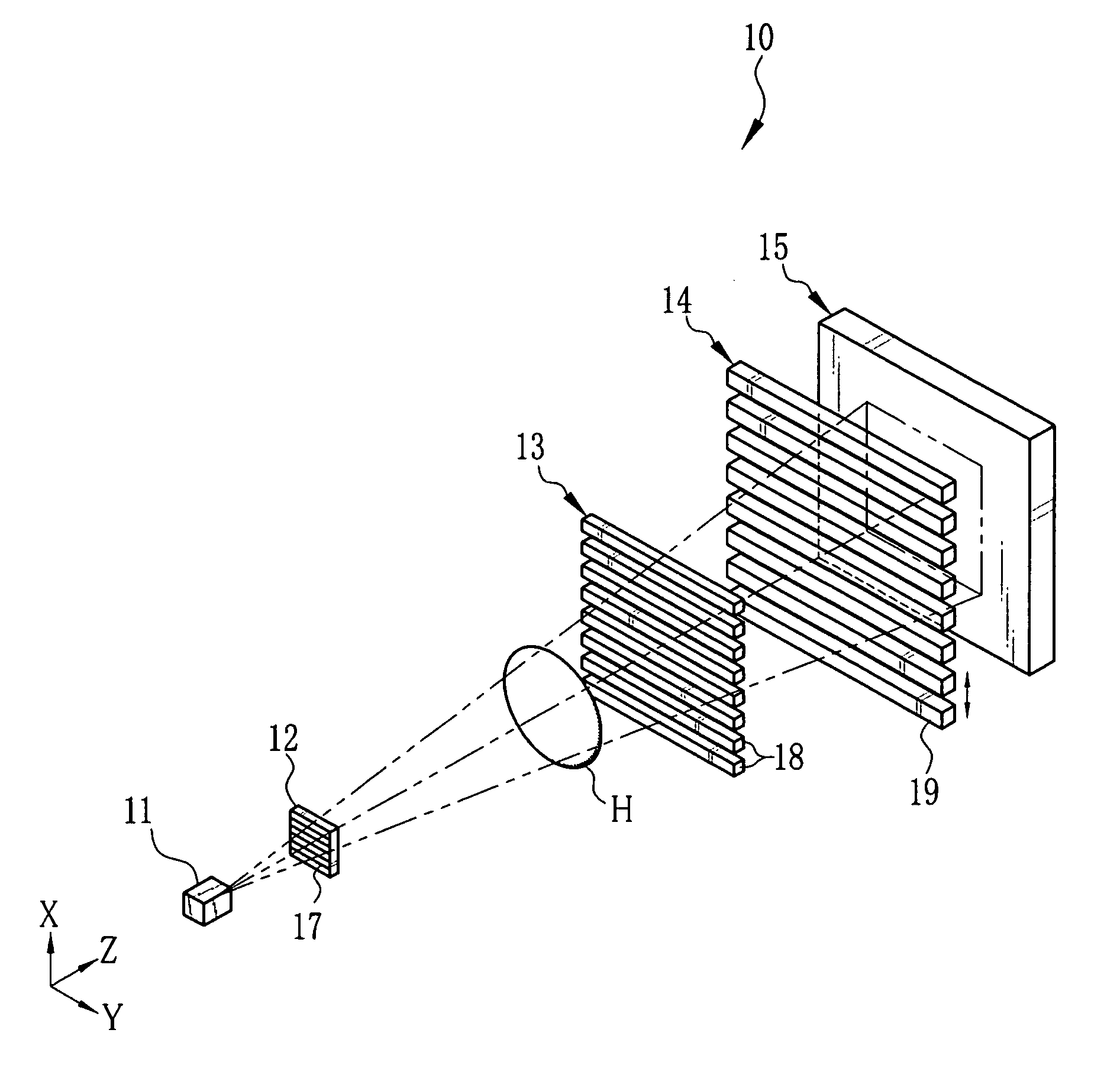
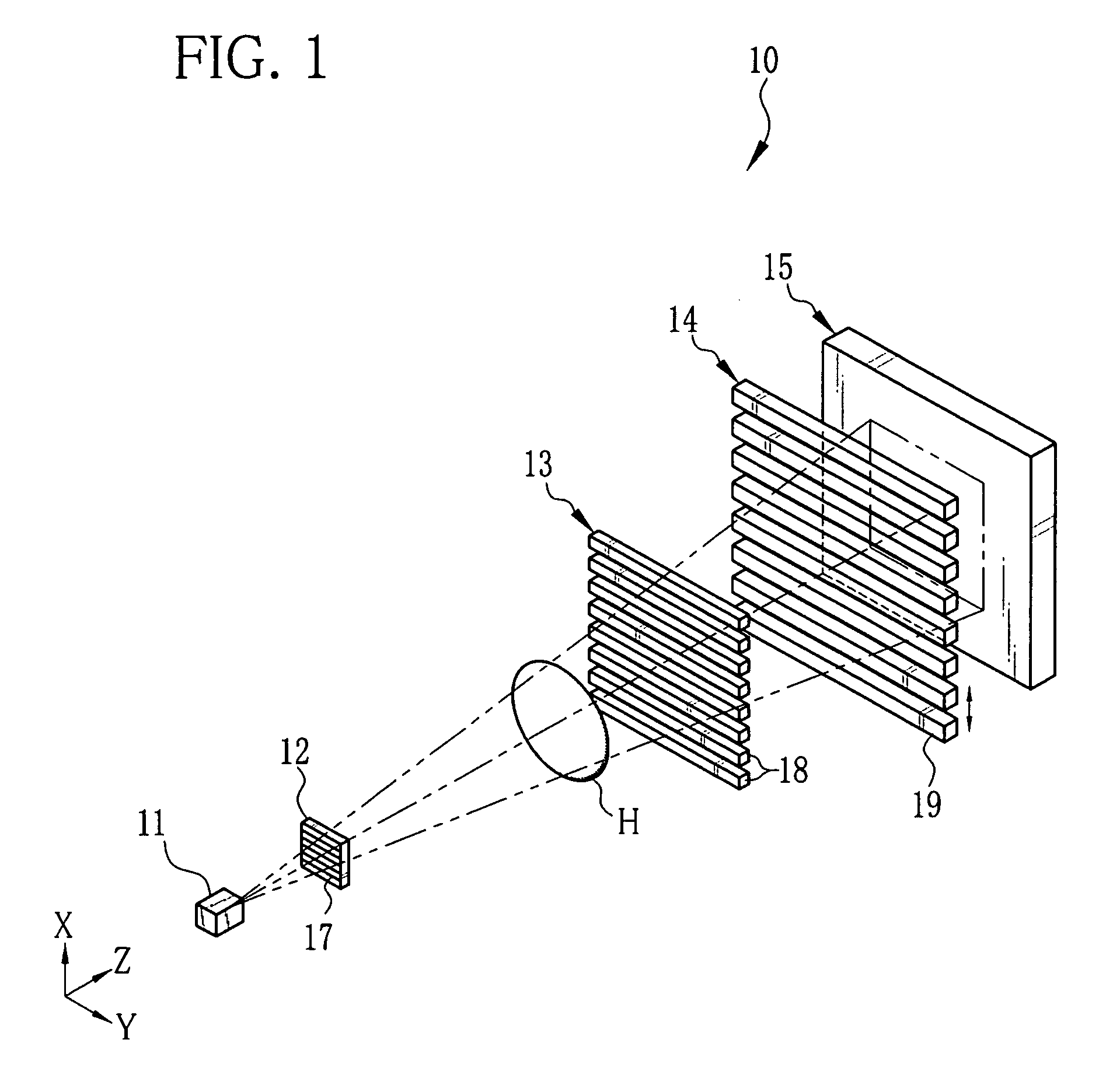
[0032]As shown in FIG. 1, an X-ray imaging system 10 according to the present invention is constituted of an X-ray source 11, a source grid 12, a first grid 13, a second grid 14, and an X-ray image detector 15. The X-ray source 11 applies X-rays to an object H disposed in a Z direction. The source grid 12 is opposite to the X-ray source 11 in the Z direction. The first grid 13 is disposed in parallel with the source grid 12 at a predetermined distance away from the source grid 12 in the Z direction. The second grid 14 is disposed in parallel with the first grid 13 at another predetermined distance away from the first grid 13 in the Z direction. The X-ray image detector 15 is opposite to the second grid 14. As the X-ray image detector 15, a flat panel detector (FPD) using semiconductor circuitry is employed, for example.

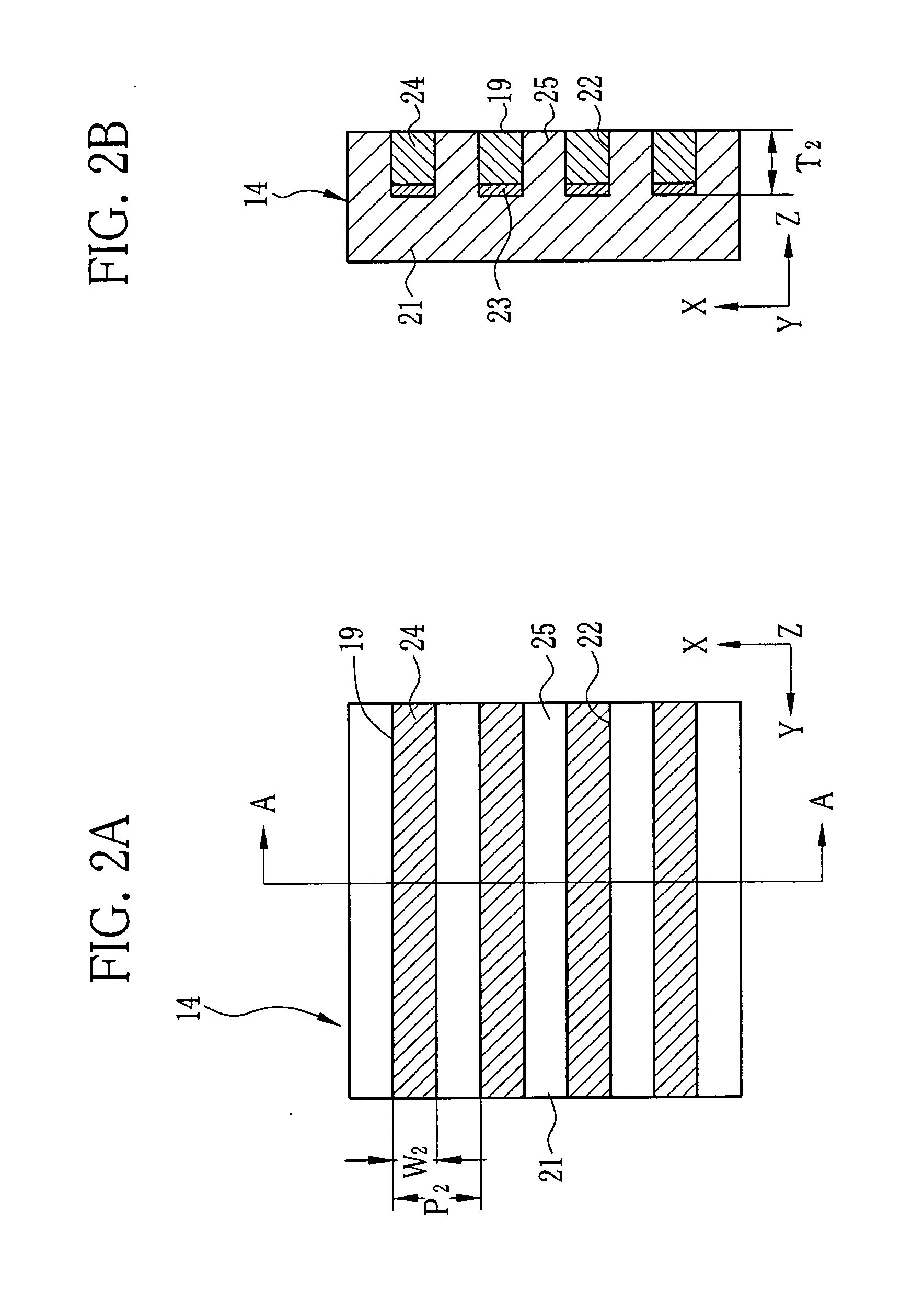
[0033]The source grid 12, the first grid 13, and the second grid 14 are X-ray absorption grids having plural X-ray absorbing portions 17, 18, and 19, respectively. Th...


PUM


Abstract

A gold colloidal solution is applied by dripping to a radio-transparent substrate having grooves with a high aspect ratio. The applied gold colloidal solution flows into the groove by capillarity, and is retained in the bottom of the groove. The radio-transparent substrate is heated from beneath by a laser beam at a part of the groove to which the gold colloidal solution has been applied, so the gold colloidal solution is vaporized and dried. Thus, gold colloidal particles remaining in the groove form a seed layer for electrolytic plating.

Description

BACKGROUND OF THE INVENTION[0001]1. Field of the Invention[0002]The present invention relates to a grid used in radiography, and a manufacturing method of the grid, and a radiation imaging system using the grid.[0003]2. Description Related to the Prior Art[0004]A radiation imaging system using the Talbot effect is devised as a type of radiation phase imaging, by which an image (hereinafter called phase contrast image) is obtained based on a phase change (angle change) of radiation transmitted through an object. For example, an X-ray imaging system using X-rays as the radiation is constituted of a first grid, a second grid, and an X-ray image detector. The first grid is disposed behind an object to be imaged. The second grid is disposed downstream from the first grid in an X-ray transmission direction by the Talbot distance, which is determined by a grid pitch of the first grid and a wavelength of the X-rays. The X-ray image detector is disposed behind the second grid. The X-rays tra...

Claims


Application Information

Patent Timeline
IPC IPC(8): G01N23/04H01L31/18G21K1/00
CPCA61B6/4035A61B6/4291G21K2207/005G21K1/025G21K1/06A61B6/484
Inventor KANEKO, YASUHISA
Owner FUJIFILM CORP
Why Eureka
Try Eureka