Active Combustion Flow Modulation Valve

a technology of active combustion and flow modulation, which is applied in the direction of valves, turbine/propulsion fuel valves, mechanical equipment, etc., can solve the problems of inability to modulate inability to develop higher frequency flow modulation applications, and inability to modulate on/off injection methods. modulation of both the amplitude and phase of fuel injection, and high operational frequency , high responsive to input drive signals

Active Publication Date: 2012-03-15
UNIVERSITY OF PITTSBURGH
View PDF8 Cites 14 Cited by
  • Summary
  • Abstract
  • Description
  • Claims
  • Application Information

AI Technical Summary

Benefits of technology

[0020]The disclosure herein provides a flow modulation valve having attributes designed to make it highly responsive to input drive signals. The assembly incorporates pressure balanced throttling components, a fast-acting coil actuator, low hysteresis movement, and an energy-dense magnetic geometry. The flow modulation valve may be utilized for applications requiring readily amenable retrofitting, small diameter working fluid lines, high operational frequency, strict controllability, and low production and maintenance cost, among othe...

Problems solved by technology

Development of higher frequency flow modulation applications, however, presents additional challenges.
These approaches have achieved some success, however the use of digital combinations to approximate a desired analog characteristic generates inherent inaccuracies and typically requires microprocessor control.
Additionally, the on/off injection methodology is unable to modulate both the amplitude and the phase of a fuel injection, unlike a proportional injection methodology.
Additionally, general size and high pressure and temperature effects on the mechanism may prohibit operations in applications where a small footprint and large variation in thermal stresses become significant.
This increases the necessary size of the spool.
As a result, for high frequency and large flow rate applications, the force and power required of the actuator in order to stroke the spool becomes significant, and single stage spool valves can become impractical in terms of size and valve geometry.
However, generating the energy density and force necessary to achieve a desired bandwidth for a given device size with a direct drive arrangement is a formidable challenge.
In some cases, the force required to accelerate the valve mass can be high, and physically large electromagnetic actuators may be required.
Additionally, impinging flows on ...

Method used


Image

  • Active Combustion Flow Modulation Valve
  • Active Combustion Flow Modulation Valve
  • Active Combustion Flow Modulation Valve

Examples


Embodiment Construction

[0032]The following description is provided to enable any person skilled in the art to use the invention and sets forth the best mode contemplated by the inventor for carrying out the invention. Various modifications, however, will remain readily apparent to those skilled in the art, since the principles of the present invention are defined herein specifically to provide a flow modulation valve capable of high speed operation in high temperature, high pressure environments.

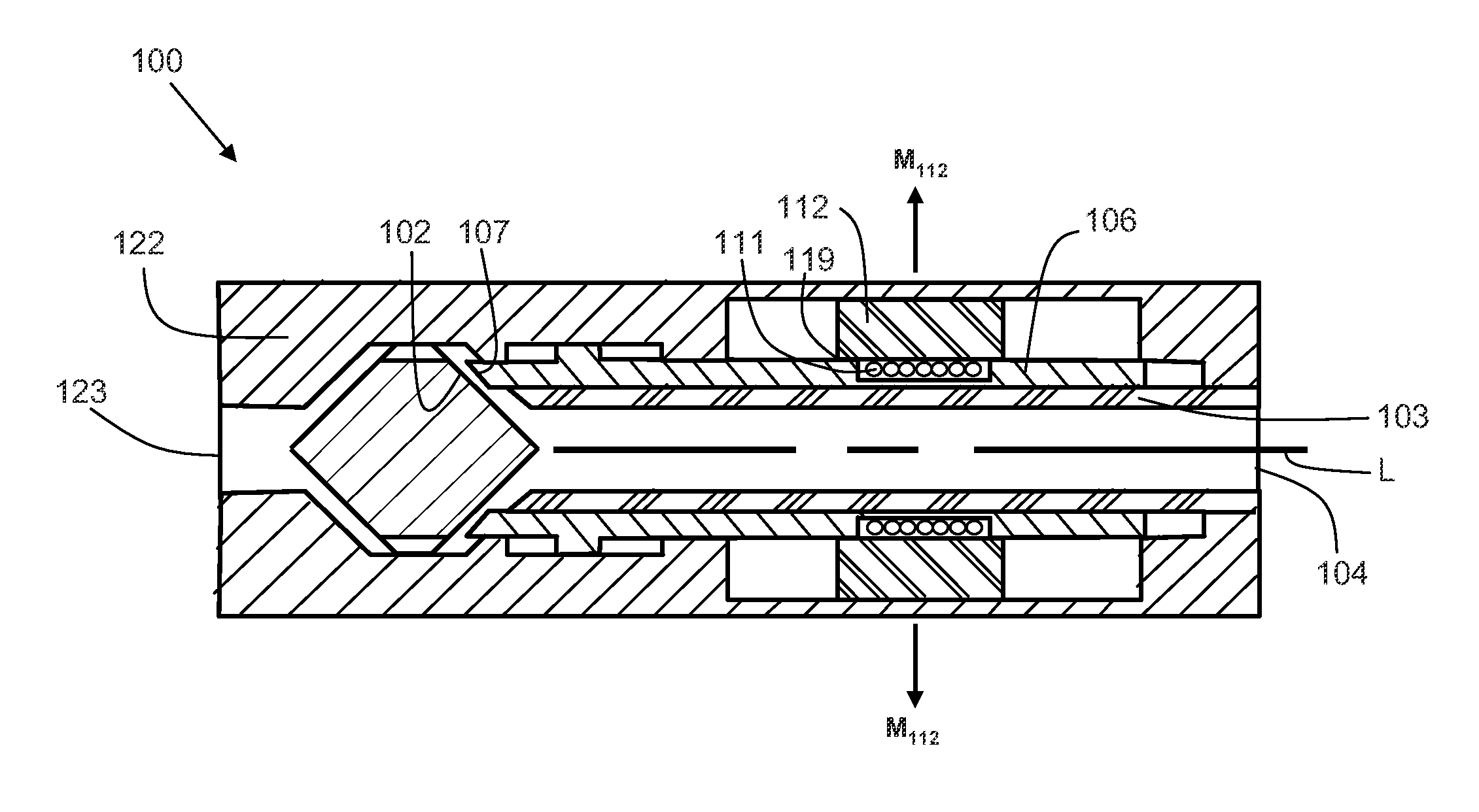
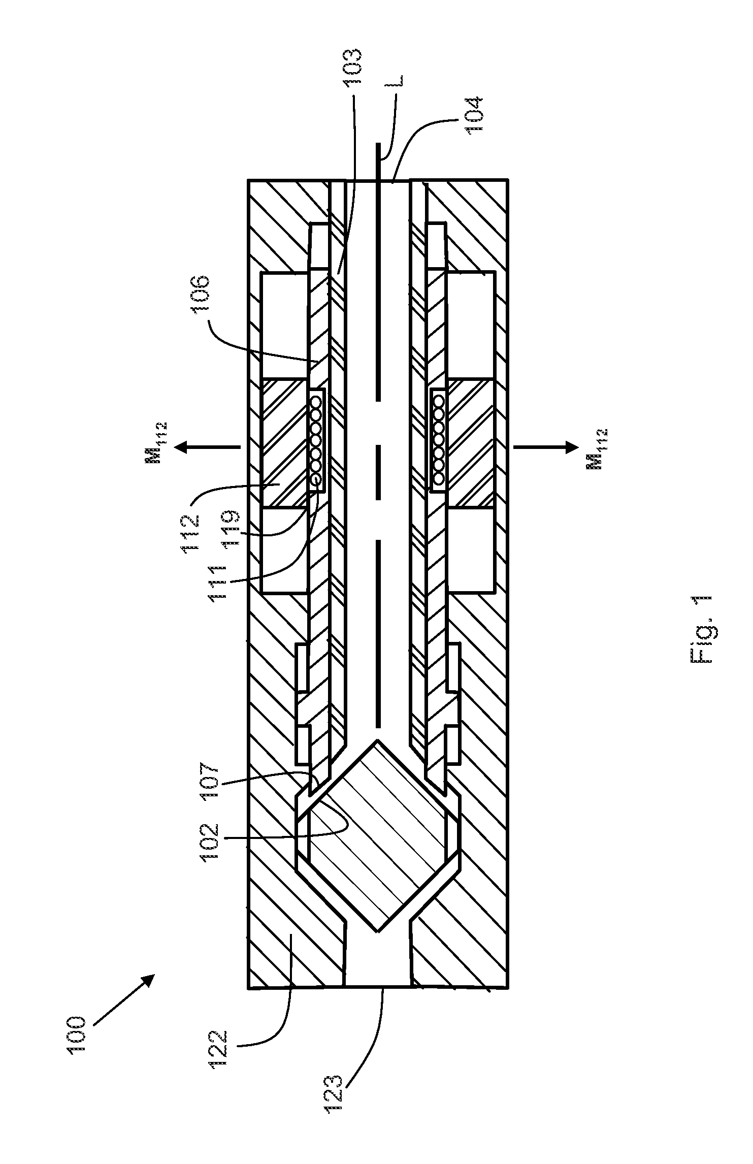
[0033]The present invention provides a flow modulation valve having attributes designed for rapid response to high frequency input drive signals. The assembly incorporates pressure balanced throttling components, a fast-acting coil actuator, low hysteresis movement, and an energy-dense magnetic geometry. The flow modulation valve may be utilized for applications requiring readily amenable retrofitting, small diameter working fluid lines, high nominal flow rates, high operational frequency, strict controllability, ...


PUM


Abstract

A flow modulation valve has a slidably translating hollow armature with at least one energizable coil wound around and fixably attached to the hollow armature. The energizable coil or coils are influenced by at least one permanent magnet surrounding the hollow armature and supported by an outer casing. Lorentz forces on the energizable coils which are translated to the hollow armature, increase or decrease the flow area to provide flow throttling action. The extent of hollow armature translation depends on the value of current supplied and the direction of translation depends on the direction of current flow. The compact nature of the flow modulation valve combined with the high forces afforded by the actuator design provide a flow modulation valve which is highly responsive to high-rate input control signals.

Description

CROSS REFERENCE TO RELATED APPLICATIONS[0001]This application claims priority to U.S. provisional application No. 61 / 383,054 filed Sep. 15, 2010, entitled “Active Combustion Flow Modulation Valve”, the contents of which are incorporated herein by reference.STATEMENT OF GOVERNMENTAL SUPPORT[0002]This invention was made with government support under grant # DE-AC26-04NT41817 awarded by the NETL / DOE. The government has certain rights in the invention.TECHNICAL FIELD[0003]A flow modulation valve having a slidably translating valve stem, arranged such that the position of one end of the valve stem relative to the valve seat defines a flow area through which a fluid flow is modulated at high frequency. The flow modulation valve utilizes an arrangement where a sliding valve stem surrounds a hollow stem support and flow is directed through the stem support before passing between the valve face and the valve seat. This provides a flowpath where radial forces on the valve stem arising from fl...

Claims


Application Information

Patent Timeline
IPC IPC(8): F16K31/08
CPCF02C7/232F16K31/0651F16K31/082F16K31/0679F16K31/0658
Inventor HENSEL, JOHN PETERBLACK, NATHANIELTHORTON, JIMMY DEANVIPPERMAN, JEFFREY STUARTLAMBETH, DAVID N.CLARK, WILLIAM W.
Owner UNIVERSITY OF PITTSBURGH
Why Eureka
Try Eureka