

Polymer pellets containing supercritical fluid and methods of making and using
- Summary
- Abstract
- Description
- Claims
- Application Information
AI Technical Summary
Benefits of technology
Problems solved by technology
Method used
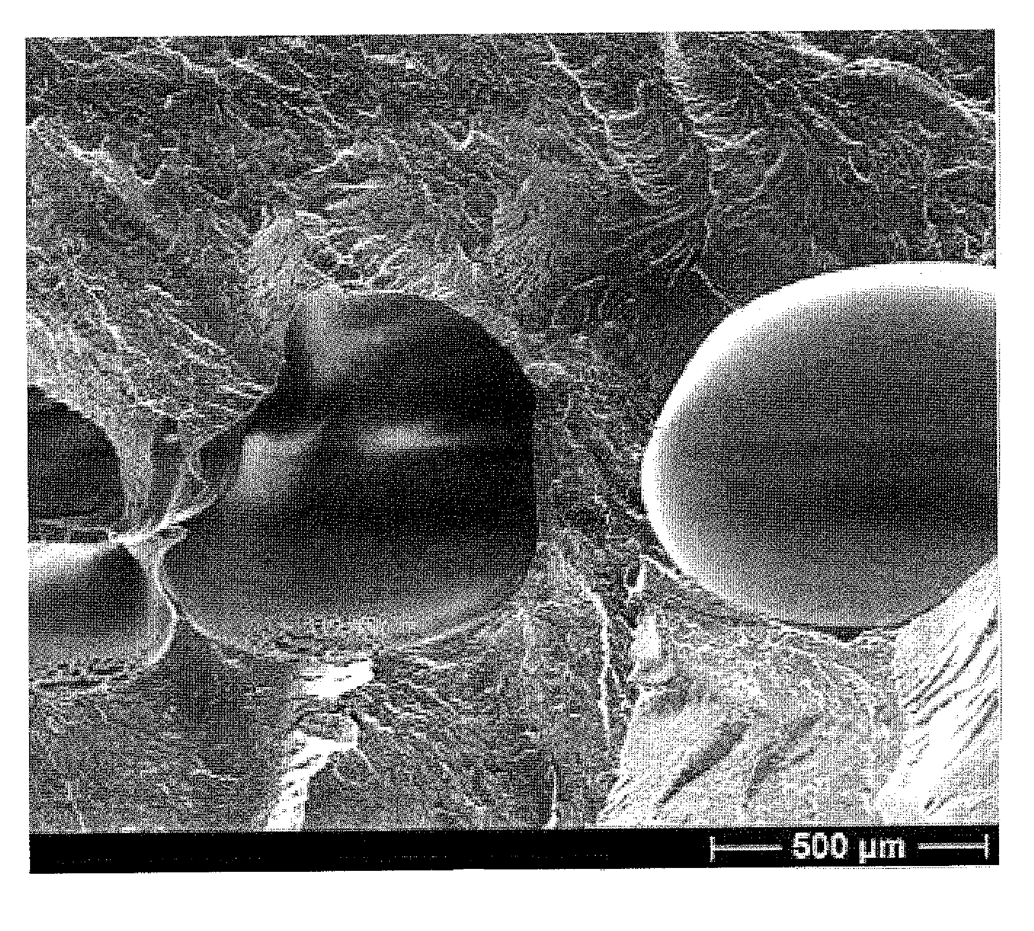
Image

Examples
example 1
Calculation of Parameters for Production of SCF-Laden Pellets
[0036]The gas flow rate for producing pre-loaded supercritical fluid pellets using a laboratory-sized extruder and an injection molding machine (an Arburg 320S) was calculated. From the calculations, it was determined that a minimum gas flow rate of 0.025 to 0.25 milliliters per minute (ml / min) would be suitable for providing nitrogen as the SCF and that a gas flow rate of 0.55 to 0.6 ml / min would be suitable for providing carbon dioxide as the SCF. These flow rate ranges would allow for the production of the desired SCF-laden pellets for the subsequent injection molding process of manufacturing foamed parts.
[0037]Some numerical estimates of various material properties, solubilities, flow rate estimates, and other operating conditions useful for the production of SCF-laden pellets are listed in Table 1 below.
TABLE 1Gas flow rate for producing SCF-laden (pre-SCF-loaded) pellets using extruder.*Gas typePropertiesCarbon dioxi...
example 2
Proposed Equipment and Set-Up for Production of SCF-Laden Pellets
[0038]Referring now to FIG. 3, an equipment set-up for the production of SCF-laden pellets is shown generally at 60. The set-up 60 includes a single screw extruder 62 (Model No. ED-N 45-30D available from Extrudex of Painesville, Ohio) having a conveying portion 63 with a single plasticizing screw, a hopper 36 into which polymer is introduced, and an injector 22 through which the SCF is introduced; a multi-strand extrusion die 64 located to receive plasticized and SCF-laden melt from the conveying portion 63; a water bath 52 to receive extruded material from the extrusion die 64; and a pelletizer 32 (Model No. SGS 100-E available from Extrudex of Painesville, Ohio) for receiving the extruded material from the water bath 52.
[0039]As is shown in FIGS. 4 and 5, the SCF-laden melt is received from the conveying portion 63 in strand form (strands 65) and fed to the water bath 52. The water bath 52 comprises an elongated tro...
example 3
Production of SCF-Laden Pellets Using LDPE and Supercritical Carbon Dioxide
[0048]The production of SCF-laden pellets was carried out under the following operating conditions:[0049]Material: LDPE (KN226, Chevron-Phillips)[0050]CO2 liquid / gas cylinder with siphon (60 bar with a full cylinder)[0051]Chiller with water set at 3 degrees C.[0052]The syringe is covered by insulation to prevent heat loss[0053]Commonly designed extruder screw (i.e. no reverse flight screws or special mixing elements)[0054]Gas refill rate: 7 ml / min.[0055]Screw speed: 30 rpm
[0056]Two modes were used to run the experiments, namely constant flow and constant pressure. In the constant flow mode, the flow rate ranged from 0.5-10 ml / min. The pressure increased during the run to 60-70 bar, at which point the gas was pumped to the extruder irregularly. In the constant pressure mode, the pressure was adjusted from 60 up to 100 bar. When the pressure exceeded 75 bar, the material was observed to foam. At a gas pressure ...
PUM
| Property | Measurement | Unit |
|---|---|---|
| Fraction | aaaaa | aaaaa |
| Fraction | aaaaa | aaaaa |
| Fraction | aaaaa | aaaaa |
Abstract
Description
Claims
Application Information