Blood processing filter and the method for manufacturing the same

a technology of filter and blood, applied in the field of blood processing filter, can solve the problems of increasing the number of occasions for removing undesirable components before blood transfusion, difficult steam sterilization, and damage to bags and tubes, etc., and achieves the effects of reducing the cost of manufacturing, reducing the number of occasions for removing undesirable components, and simplifying the manufacturing process

Active Publication Date: 2012-03-22
ASAHI KASEI MEDICAL CO LTD
View PDF7 Cites 21 Cited by
  • Summary
  • Abstract
  • Description
  • Claims
  • Application Information

AI Technical Summary

Benefits of technology

[0017]An object of the present invention is to provide a blood processing filter that, without leading to a risk of a welding defect, complicating the manufacturing process, or increasing costs, can avoid a situation in which a flow is inhibited and filtering performance is lowered due to adherence or the like between an outlet-side container and a filter element of a flexible filter, can effectively utilize the entire filter element, and can simultaneously achieve a high flow rate and high filtering performance.

Problems solved by technology

Since microaggregates and leukocytes included in these blood preparations cause various side effects during blood transfusion, the number of occasions for removing these undesirable components before blood transfusion has been increasing.
However, because the container used in such a filter has a low level of air permeability, there is the problem that it is difficult to apply steam sterilization, which is widely used as a sterilization process in blood collection-separation sets.
At such time, a hard container may damage bags and tubes, or the hard container itself may not withstand the stress and may break during centrifugation.
In the case of the filter that includes a flexible container, there is a tendency for the flexibility of the container itself to cause the container to swell like a balloon due to the positive pressure, thereby pressing the filter element against the container on the outlet side.
Hence, there is a tendency for the outlet side of the filter to become a negative pressure due to this action, and the flexible container is liable to adhere to the filter element.
That is, it has been pointed out previously that in the case of a filter that uses a flexible container, there is a problem that there is a strong tendency for the filter element to adhere to the outlet-side container due to a dual force, and as a result the flow of blood is obstructed and an adequate flow rate can not be obtained.
However, in a case in which a separate member such as a connecting rod or a screen is inserted, because it is required to perform welding precisely when welding the separate member to the container, there are the problems that a welding defect may occur, the manufacturing process, is complicated, and the manufacturing cost is increased by the use of additional materials.
Furthermore, in the case of providing concavities and convexities on the internal surface of a container, there is the problem that the concavities and convexities on the internal surface of the container may induce a welding defect or may decrease the pressure resistance when the container material and the filter element are welded together.
As described above, when the conventional technology is investigated from the point of view of a disadvantage caused by negative pressure that arises on the filter outlet side, in other words, from the point of view of how to secure a space that can serve as a passage for blood to pass through between the container and the filter element that are attempting to adhere to each other, it is found that the conventional technology is not necessarily satisfactory.

Method used


Image

  • Blood processing filter and the method for manufacturing the same
  • Blood processing filter and the method for manufacturing the same
  • Blood processing filter and the method for manufacturing the same

Examples


example 1

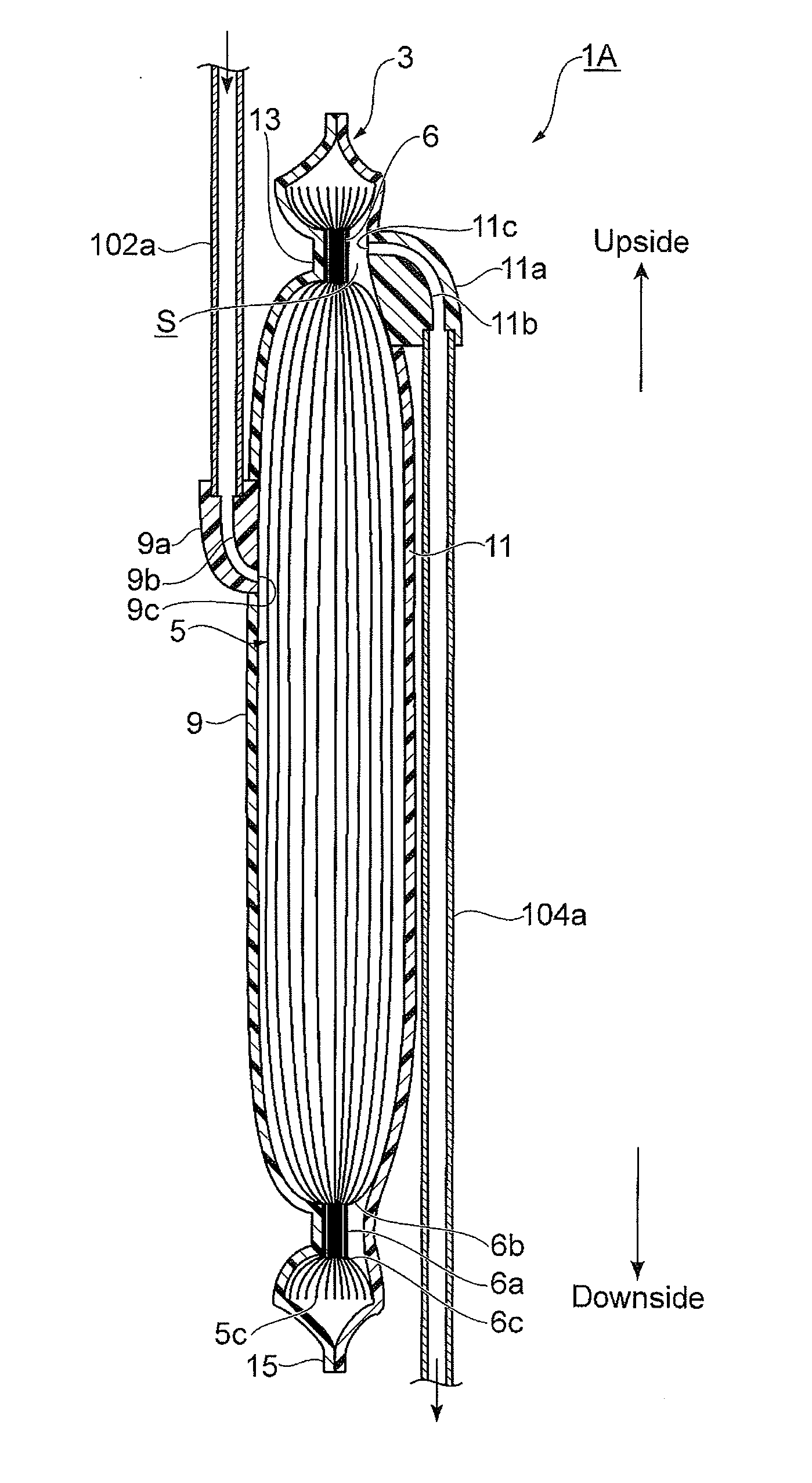
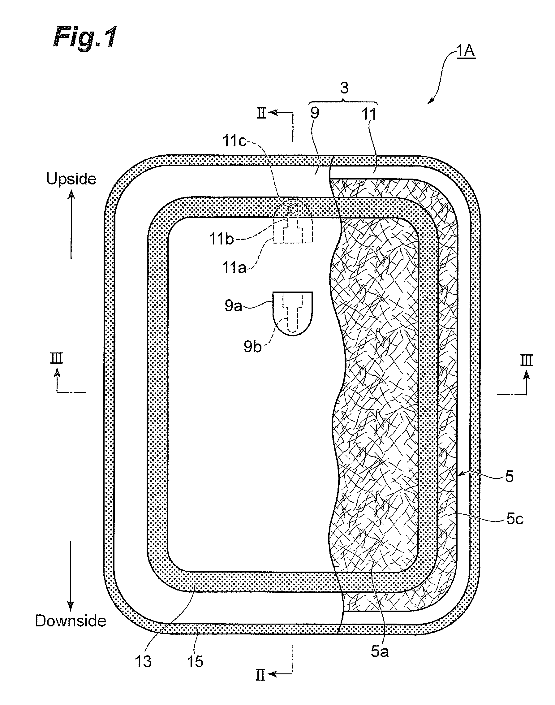
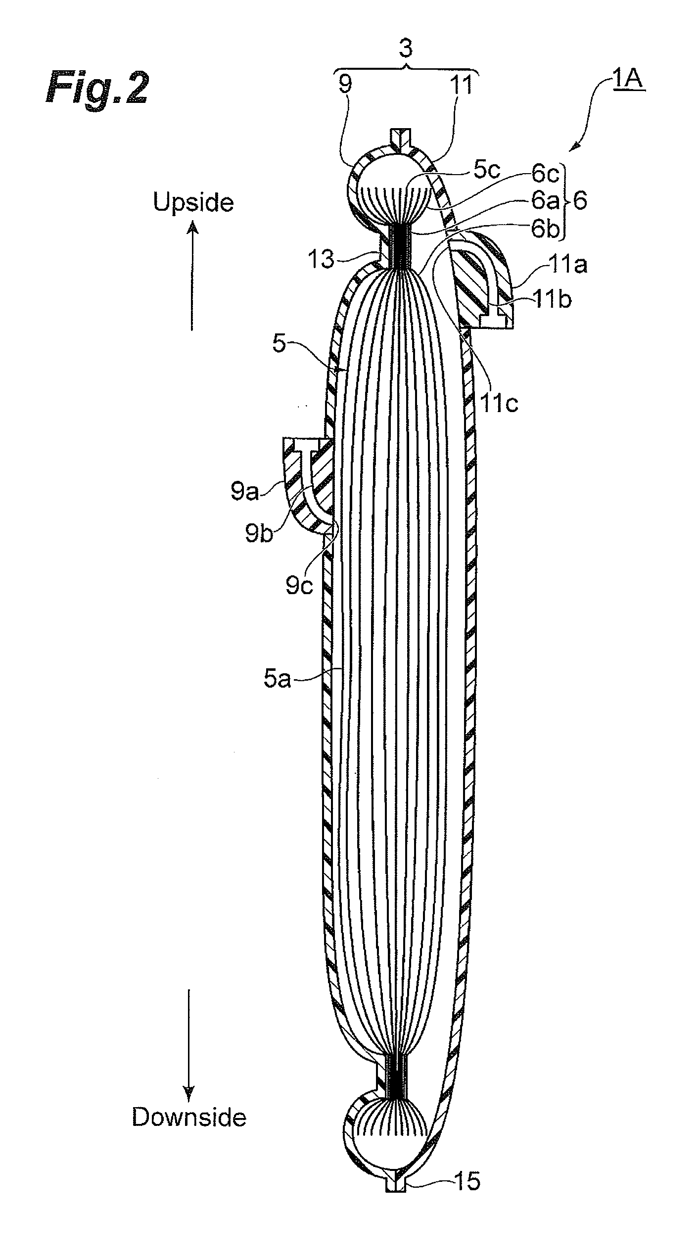
[0079]A filter including an inlet-side container (inlet-side flexible container), an outlet-side container (outlet-side flexible container) and a filter element was prepared, and an inlet port thereof was connected to a pre-filtration liquid reservoir bag via an inlet-side circuit having a length of 50 cm. An outlet port of the filter was connected to a post-filtration liquid recovery bag via an outlet-side circuit having a length of 100 cm. A tube made of soft polyvinyl chloride having an internal diameter of 2.9 mm and an external diameter of 4.2 mm was used for the inlet-side circuit and the outlet-side circuit.

[0080]In preparing the filter, an effective filtering portion was formed in a rectangular shape in which an inner side of an inside seal part (first seal part) had a longitudinal dimension of 74 cm and a horizontal dimension of 57 cm, a corner portion was formed as a curve, and an effective filtration area of 42×10−4 (m2) was provided. As the filter element, four sheets of...

example 2

[0084]Filtering was carried out using a filter assembled by the same method as in Example 1, except that sealing and assembly were performed so that the outlet opening of the outlet port overlapped with the uppermost portion of the first seal part (valley part).


PUM

PropertyMeasurementUnit
heightaaaaaaaaaa
lengthaaaaaaaaaa
lengthaaaaaaaaaa

Abstract

This invention relates to a blood processing filter including a band-shaped first seal part that seals an inlet-side flexible container of the blood processing filter and a filter element of the blood processing filter so as to surround an inlet port, and an annular second seal part that seals at least the inlet-side flexible container and an outlet-side flexible container and is formed surrounding the first seal part at a position that is closer to an outer edge than the first seal part. A valley part corresponding to the first seal part is provided on an outlet side of the filter element. An outlet opening that communicates with an inside of the outlet-side flexible container is formed in the outlet port. At least one portion of the outlet opening is arranged so as to overlap with the valley part.

Description

BACKGROUND OF THE INVENTION[0001]1. Field of the Invention[0002]The present invention relates to a blood processing filter for removing undesirable components such as aggregates and leukocytes from blood. In particular, the present invention relates to a precise and disposable blood processing filter for removing microaggregates and leukocytes which may cause side effects from whole blood preparations, erythrocyte preparations, thrombocyte preparations, blood plasma preparations and the like for blood transfusion, as well as a method for manufacturing the blood processing filter.[0003]2. Related Background Art[0004]It is becoming common for whole blood collected from a donor to be separated into blood component preparations such as an erythrocyte preparation, a thrombocyte preparation, and a blood plasma preparation and stored for transfusion. Since microaggregates and leukocytes included in these blood preparations cause various side effects during blood transfusion, the number of ...

Claims


Application Information

Patent Timeline
Patent Type & Authority Applications(United States)
IPC IPC(8): B01D29/05B23P11/00
CPCA61M1/02Y10T29/49826A61M1/3636A61M2202/0439A61M1/34A61M1/0218B01D29/0093B01D29/05A61M2202/0431A61M2205/75
Inventor YOKOMIZO, TOMOHISAMIURA, MORIKAZU
Owner ASAHI KASEI MEDICAL CO LTD
Why Eureka
Try Eureka