
Solid electrolytic capacitor

a solid electrolytic capacitor and capacitor technology, applied in the direction of liquid electrolytic capacitors, casings/cabinets/drawers, electrical equipment casings/cabinets/drawers, etc., can solve the problems of difficult control of the thickness of the carbon layer, cracks at the time of exterior covering, and the characteristics of solid electrolytic capacitors deteriorate, so as to achieve the effect of improving the characteristics

Active Publication Date: 2012-03-29
SANYO ELECTRIC CO LTD
View PDF2 Cites 0 Cited by
  • Summary
  • Abstract
  • Description
  • Claims
  • Application Information

AI Technical Summary

Benefits of technology

[0008]The present invention was made to solve the above-described problems, and has an object to provide a solid electrolytic capacitor that can be improved in characteristics.
[0009]To solve the above-described object, the inventor of the present invention intensely studied means for reducing the gap left between the conductive polymer layer and the silver paste layer in the case of forming the silver paste layer without forming the carbon layer. As a result, the inventor found out that the solid electrolytic capacitor can be improved in characteristics without forming the carbon layer, by using an imide-based polymer as a binder resin of the silver paste layer.
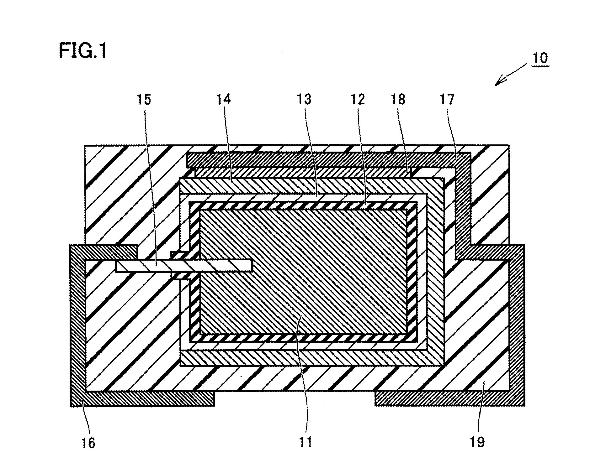
[0011]According to the solid electrolytic capacitor of the present invention, the cathode layer is a silver paste layer having an imide-based polymer as a binder resin. Since the imide-based polymer comes into close contact with the solid electrolytic layer, the gap between the silver paste layer and the solid electrolytic layer can be reduced without forming a carbon layer. This can suppress deterioration in characteristics that would result from the gap between the cathode layer and the solid electrolytic layer. Further, since a carbon layer can be omitted, deterioration in characteristics that would result from formation of a carbon layer can be prevented. A solid electrolytic capacitor that can be improved in characteristics can thus be achieved.
[0013]Since the surface of the solid electrolytic layer containing polypyrrole is smooth, a gap is likely to be left if a silver paste layer is formed directly thereon. However, by using an imide-based polymer as a binder resin of the silver paste layer, the silver paste layer in contact with the solid electrolytic layer containing polypyrrole can be formed with a reduced gap. A solid electrolytic capacitor that can be improved in characteristics can thus be achieved, even when the solid electrolytic layer contains polypyrrole.
[0014]As described above, according to the solid electrolytic capacitor of the present invention, characteristics can be improved.

Problems solved by technology

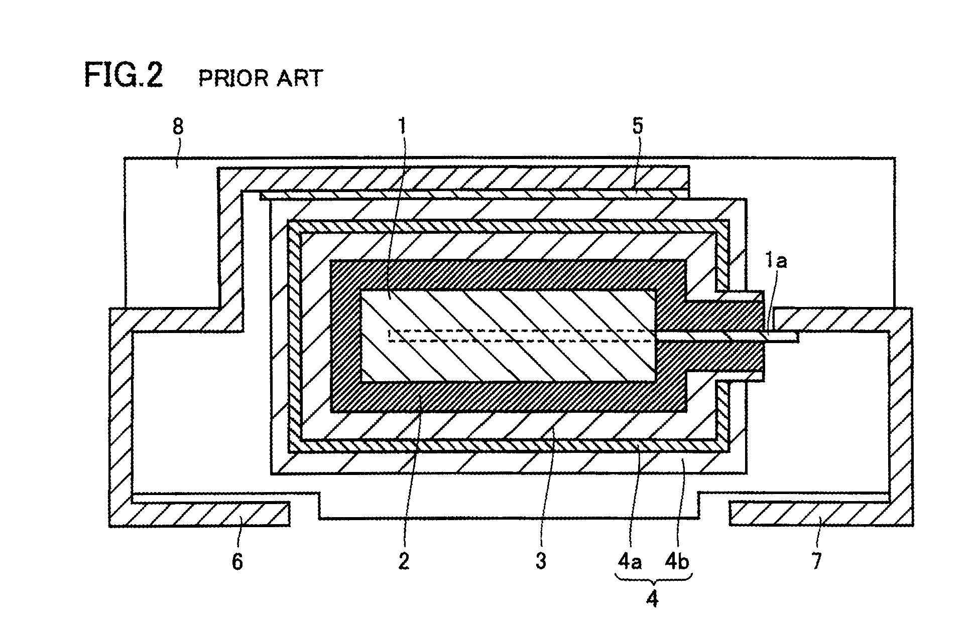
The solid electrolytic capacitor disclosed in Japanese Patent Laying-Open No. 2009-10238 has carbon layer 4a. When forming carbon layer 4a, it is difficult to control the thickness of the carbon layer.
If carbon layer 4a is formed thick, cracks will be likely to occur at the time of exterior covering.
This raises a problem in that the solid electrolytic capacitor deteriorates in characteristics.
Another possible technique is to form silver paste layer 4b so as to contact conductive polymer layer 3 without forming carbon layer 4a. In this case, however, a gap is left between conductive polymer layer 3 and silver paste layer 4b. This raises a problem in that the solid electrolytic capacitor deteriorates in characteristics.

Method used


Image

  • Solid electrolytic capacitor
  • Solid electrolytic capacitor
  • Solid electrolytic capacitor

Examples


example 1

Of the Present Invention

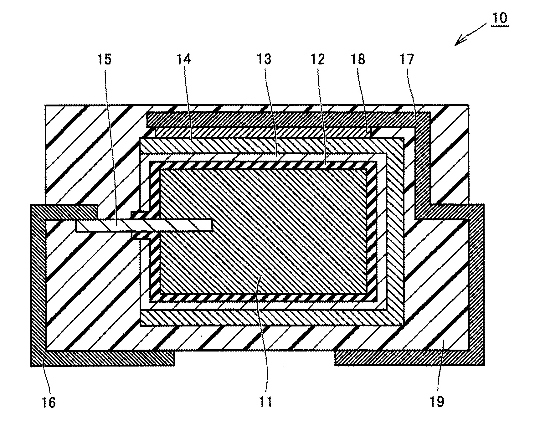
[0044]In Example 1 of the present invention, solid electrolytic capacitor 10 shown in FIG. 1 was fabricated basically in accordance with the method of fabricating a solid electrolytic capacitor of the above-described embodiment.

[0045]Specifically, first, tantalum powder was prepared, and was molded into rectangular solid with one end of anode lead 15, which was a rod-like member, in the longitudinal direction embedded in the tantalum powder. Then, this was sintered to prepare anode element 11 with one end of anode lead 15 embedded therein.

[0046]Then, anode element 11 was immersed in a phosphoric acid solution, and a voltage was applied, thereby forming dielectric layer 12 made of Ta2O5 at the surface of anode element 11.

[0047]Then, anode element 11 with dielectric layer 12 formed thereon was immersed in an electrolytic polymerization liquid containing polypyrrole to form solid electrolytic layer 13. Drying followed to form solid electrolytic layer 13 on diele...


PUM


Abstract

A solid electrolytic capacitor includes an anode element, a dielectric layer, a solid electrolytic layer, and a cathode layer. The dielectric layer is formed on the anode element. The solid electrolytic layer is formed on the dielectric layer. The cathode layer is formed so as to contact the solid electrolytic layer. The cathode layer is a silver paste layer having an imide-based polymer as a binder resin. A solid electrolytic capacitor that can be improved in characteristics can thus be obtained.

Description

[0001]This nonprovisional application is based on Japanese Patent Application No. 2010-214038 filed on Sep. 24, 2010 with the Japan Patent Office, the entire contents of which are hereby incorporated by reference.BACKGROUND OF THE INVENTION[0002]1. Field of the Invention[0003]The present invention relates to a solid electrolytic capacitor.[0004]2. Description of the Related Art[0005]As a conventional solid electrolytic capacitor, Japanese Patent Laying-Open No. 2009-10238 is mentioned, for example. FIG. 2 is a schematic sectional view showing a structure of the solid electrolytic capacitor disclosed in Japanese Patent Laying-Open No. 2009-10238. With reference to FIG. 2, the solid electrolytic capacitor of Japanese Patent Laying-Open No. 2009-10238 includes an anode element 1, a dielectric layer 2 formed at the surface of anode element 1, a conductive polymer layer 3 formed on dielectric layer 2, and a cathode layer 4 formed on conductive polymer layer 3. Cathode layer 4 has a carbo...

Claims


Application Information

Patent Timeline
IPC IPC(8): H01G9/025H01G9/042
CPCH01G9/028H01G9/15H01G9/042H01G9/0425
Inventor MATSUOKA, KEIKO
Owner SANYO ELECTRIC CO LTD
Learn More