Green Emitting Phosphor
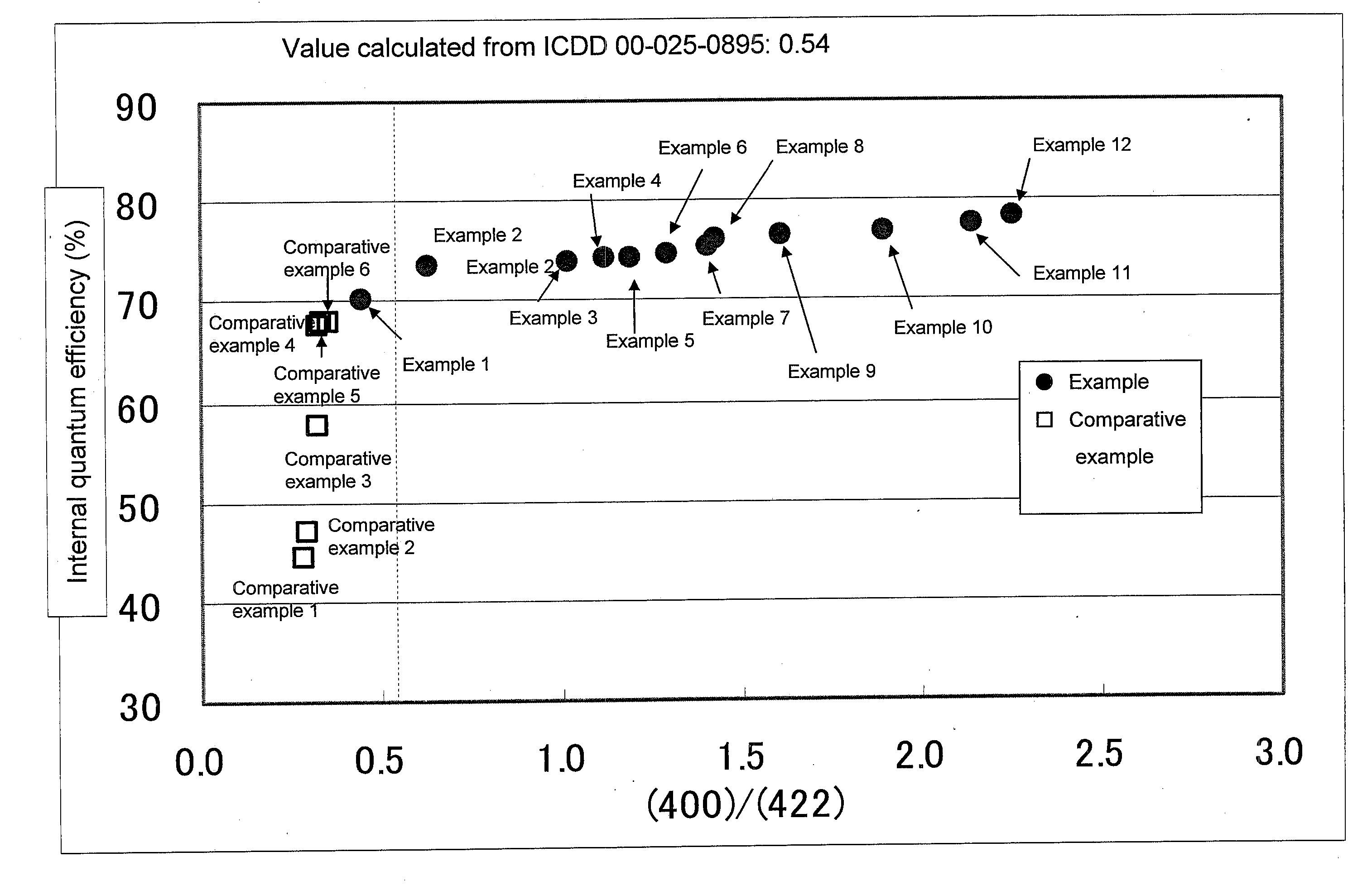
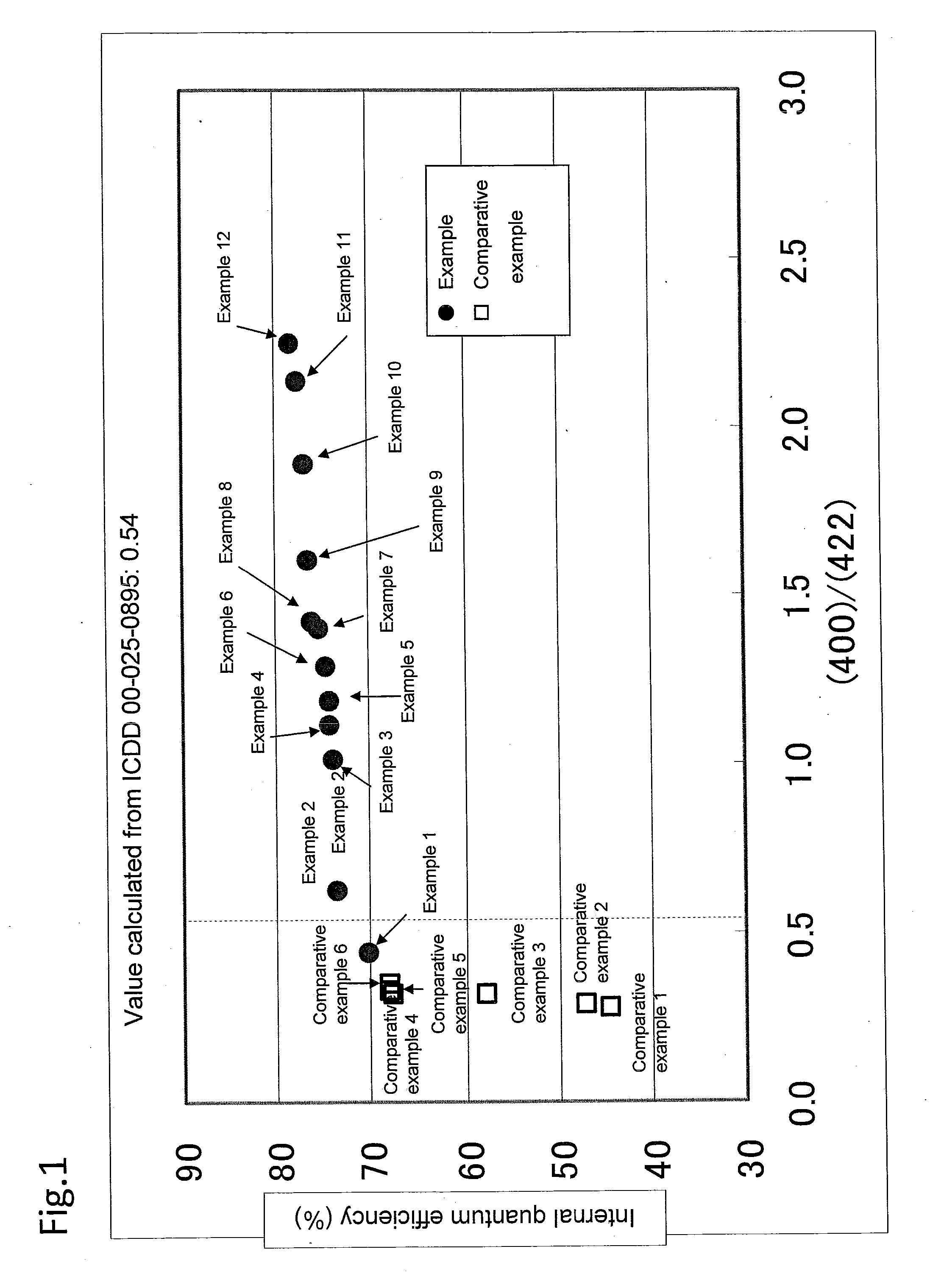
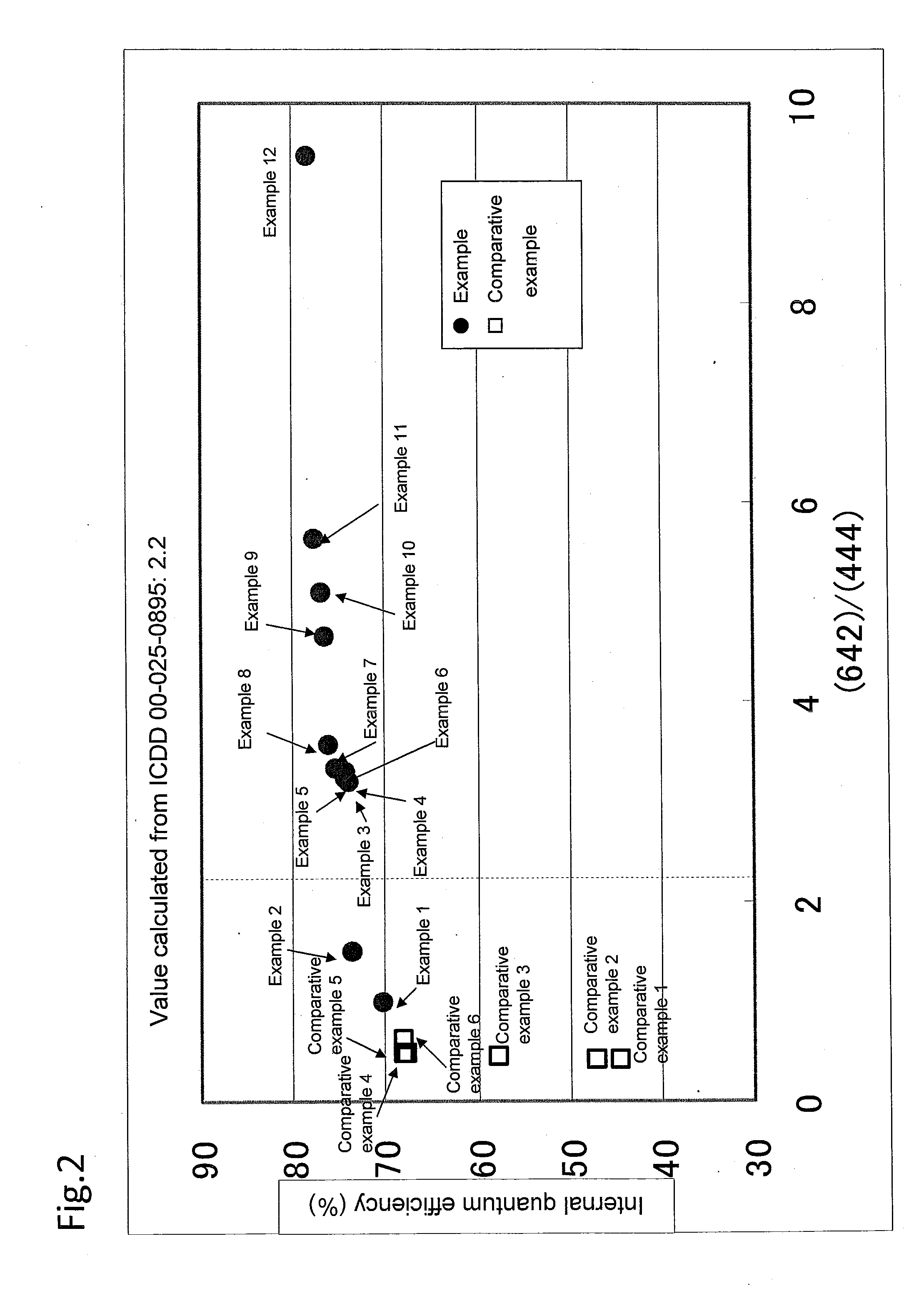
a green emitting phosphor and green technology, applied in the direction of discharge tube luminescent screen, discharge tube/lamp details, luminescent composition, etc., can solve the problems of poor color rendering properties and the inability to show the colors illuminated by natural light, and achieve high internal quantum efficiency
- Summary
- Abstract
- Description
- Claims
- Application Information
AI Technical Summary
Benefits of technology
Problems solved by technology
Method used
Image

Examples
example 1
[0114]Using SrS, Ga2S3 and EuS as starting raw materials, SrS and Ga2S3 were mixed so that the atomic ratio Ga / Sr was 1.98 and EuS was mixed so as to have 1.0 mol % with respect to Sr, which were mixed for 100 minutes with a paint shaker using a Ø3 mm zirconia ball as a medium. The obtained mixture was fired in a hydrogen sulfide atmosphere at 1130° C. for 4 hours. Next, the fired material was crushed for one minute with an automatic mortar grinder (“ALM-360T” manufactured by Nitto Kagaku Co.), and using sieves with 140 mesh and 440 mesh openings, the material under the sieve with 140 mesh opening and above the sieve with 440 mesh opening was recovered to obtain a phosphor powder sample.
example 2
[0115]Using SrS, Ga2S3 and EuS as starting raw materials, SrS and Ga2S3 were mixed so that the atomic ratio Ga / Sr was 2.00, and while EuS was mixed so as to have 1.0 mol % with respect to Sr, MgCl2 was mixed as flux so as to have 0.5wt % with respect to SrGa2S4, which were mixed for 100 minutes with a paint shaker using a Ø3 mm zirconia ball as a medium. The obtained mixture was fired in a hydrogen sulfide atmosphere at 1100° C. for 4 hours. Next, the fired material was crushed for one minute with an automatic mortar grinder (“ALM-360T” manufactured by Nitto Kagaku Co.), and using sieves with 140 mesh and 440 mesh openings, the material under the sieve with 140 mesh opening and above the sieve with 440 mesh opening was recovered to obtain a phosphor powder (sample).
example 3
[0116]Using SrS, Ga2S3 and EuS as starting raw materials, SrS and Ga2S3 were mixed so that the atomic ratio Ga / Sr was 2.15, and EuS was mixed so as to have 1.0 mol % with respect to Sr, which were mixed for 100 minutes with a paint shaker using a Ø3 mm zirconia ball as a medium. The obtained mixture was fired in a hydrogen sulfide atmosphere at 1100° C. for 6 hours. Next, the fired material was crushed for one minute with an automatic mortar grinder (“ALM-360T” manufactured by Nitto Kagaku Co.), furthermore, annealing in an argon atmosphere at 1100° C. for 4 hours was carried out, and using sieves with 140 mesh and 440 mesh openings, the material under the sieve with 140 mesh opening and above the sieve with 440 mesh opening was recovered to obtain a phosphor powder (sample).
PUM
| Property | Measurement | Unit |
|---|---|---|
| particle sizes | aaaaa | aaaaa |
| particle sizes | aaaaa | aaaaa |
| particle sizes | aaaaa | aaaaa |
Abstract
Description
Claims
Application Information
 - R&D
- Intellectual Property
- Life Sciences
- Materials
- Tech Scout
- Unparalleled Data Quality
- Higher Quality Content
- 60% Fewer Hallucinations
Browse by: Latest US Patents, China's latest patents, Technical Efficacy Thesaurus, Application Domain, Technology Topic, Popular Technical Reports.
© 2025 PatSnap. All rights reserved.Legal|Privacy policy|Modern Slavery Act Transparency Statement|Sitemap|About US| Contact US: help@patsnap.com