
Skewed radio frequency coil arrays for magnetic resonance imaging

a radio frequency coil array and magnetic resonance imaging technology, applied in the field of magnetic resonance imaging (“ mri”) systems, can solve the problems of increasing the total number of coil elements, and requiring many minutes to acquire the necessary data

Inactive Publication Date: 2012-04-05
MAYO FOUND FOR MEDICAL EDUCATION & RES
View PDF4 Cites 3 Cited by
  • Summary
  • Abstract
  • Description
  • Claims
  • Application Information

AI Technical Summary

Benefits of technology

[0014]The present invention overcomes the aforementioned drawbacks by providing a radio frequency (“RE”) coil array that includes coil elements with a skewed coil geometry that provides improved performance over standard rectangular geometries in performing acceleration, for example, along the slice-encode direction for three-dimensional axial acquisitions.
[0015]In accordance with one aspect of the invention, a radio frequency (RF) coil array configured to be coupled to a magnetic resonance imaging (MRI) system is disclosed that includes an electrical coupling configured to provide electrical communication between an RF system that forms a part of the MRI system and the RF coil array and a plurality of conductive coil elements. Each conductive coil element includes a conductive coil loop forming a quadrilateral extending along a first direction away from the electrical coupling and along a second direction extending non-perpendicular to the first direction to form a skew angle between the first direction and a line extending from the second direction and perpendicular to the second direction. The array also includes a coil substrate coupled to the plurality of conductive coil elements to arrange the plurality of conductive coil elements in the coil array and facilitate arrangement of the plurality of conductive coil elements about a subject for imaging during an MRI imaging process.

Problems solved by technology

Depending on the technique used, many MR scans currently require many minutes to acquire the necessary data used to produce medical images.
In 3DFT axial acquisition, however, this arrangement will not provide variation of sensitivity profiles in the S / I direction, which is the slice-encoding or z-direction.
This potentially increases the total number of coils elements, which increases hardware costs and the computational burden of image reconstruction.
Attempting z-acceleration with rows of coils works well in general, but experiences high noise amplification when the product of coil length and the acceleration factor approaches or exceeds the slab FOV.

Method used


Image

  • Skewed radio frequency coil arrays for magnetic resonance imaging
  • Skewed radio frequency coil arrays for magnetic resonance imaging
  • Skewed radio frequency coil arrays for magnetic resonance imaging

Examples


Embodiment Construction

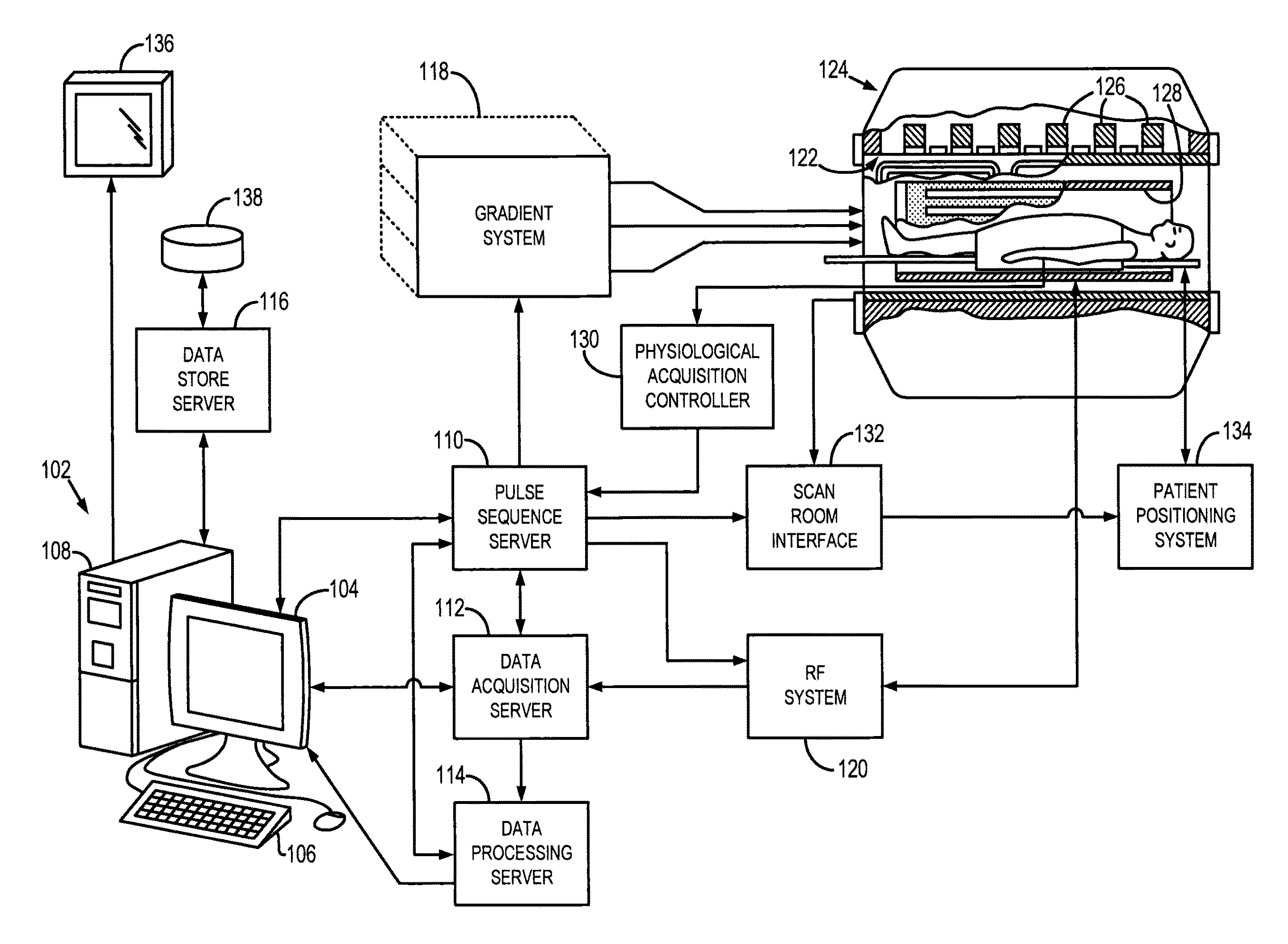
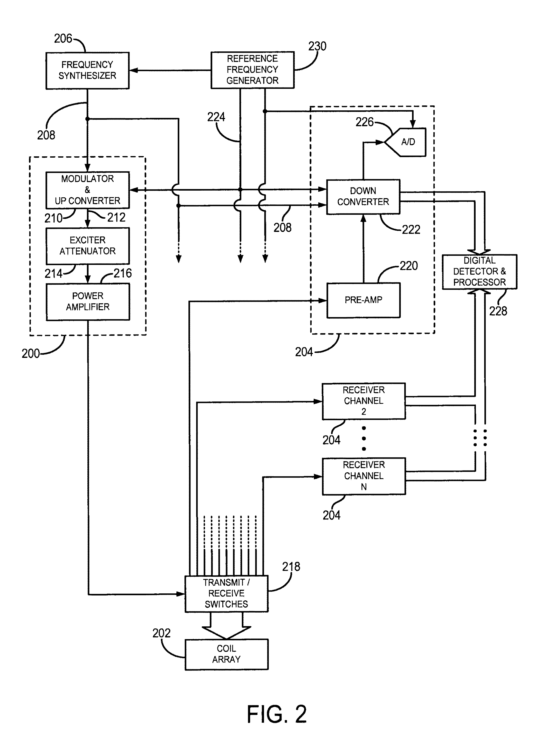
[0024]Referring particularly to FIG. 1, an exemplary magnetic resonance imaging (MRI) system 100 is shown. The MRI system 100 includes a workstation 102 having a display 104 and a keyboard 106. The workstation 102 includes a processor 108, such as a commercially available programmable machine running a commercially available operating system. The workstation 102 provides the operator interface that enables scan prescriptions to be entered into the MRI system 100. The workstation 102 is coupled to four servers: a pulse sequence server 110; a data acquisition server 112; a data processing server 114, and a data store server 116. The workstation 102 and each server 110, 112, 114 and 116 are connected to communicate with each other.

[0025]The pulse sequence server 110 functions in response to instructions downloaded from the workstation 102 to operate a gradient system 118 and a radiofrequency (RF) system 120. Gradient waveforms necessary to perform the prescribed scan are produced and a...


PUM


Abstract

A radio frequency (RF) coil array configured for use with a magnetic resonance imaging (MRI) system and that includes coil elements with a skewed coil geometry is provided. The coil elements are skewed with respect to a given direction, such as the slice-encoding direction of an MRI system, such that a variation in spatial sensitivity along that direction is provided. This spatial sensitivity variation allows for parallel imaging acceleration along the direction of the variation, which provides improved performance over standard rectangular geometries in performing acceleration along the slice-encode direction for three-dimensional axial acquisitions.

Description

CROSS-REFERENCE[0001]This application is based on, claims priority to, and incorporates herein by reference U.S. Provisional Application Ser. No. 61 / 386,990, filed Sep. 27, 2010, and entitled “SKEWED RADIO FREQUENCY COIL ARRAYS FOR MAGNETIC RESONANCE IMAGING.”STATEMENT REGARDING FEDERALLY SPONSORED RESEARCH[0002]This invention was made with government support under grant number NIH EB000212, awarded by the National Institutes of Health. The government has certain rights in the invention.FIELD OF THE INVENTION[0003]The field of the invention is magnetic resonance imaging (“MRI”) systems. More particularly, the invention relates to radio frequency (“RF”) coils for use with parallel MRI techniques.BACKGROUND OF THE INVENTION[0004]Magnetic resonance imaging (“MRI”) uses the nuclear magnetic resonance (“NMR”) phenomenon to produce images. When a substance such as human tissue is subjected to a uniform magnetic field (polarizing field B0), the individual magnetic moments of the nuclei in ...

Claims


Application Information

Patent Timeline
Patent Type & Authority Applications(United States)
IPC IPC(8): G01R33/3415
CPCG01R33/5611G01R33/3415
Inventor TAN, EK T.RIEDERER, STEPHEN J.
Owner MAYO FOUND FOR MEDICAL EDUCATION & RES
Learn More