
Ceramic particles and coating compositions including said particles

a technology of ceramic particles and coating compositions, applied in the field of coating compositions, can solve the problems of environmental safety hazards, long-term corrosion protection, and important damage to the aircraft structure, and achieve the effect of stable release profile of inhibitors

Inactive Publication Date: 2012-04-12
CERAMISPHERE +1
View PDF9 Cites 26 Cited by
  • Summary
  • Abstract
  • Description
  • Claims
  • Application Information

AI Technical Summary

Benefits of technology

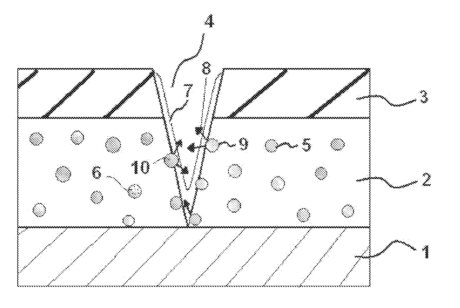
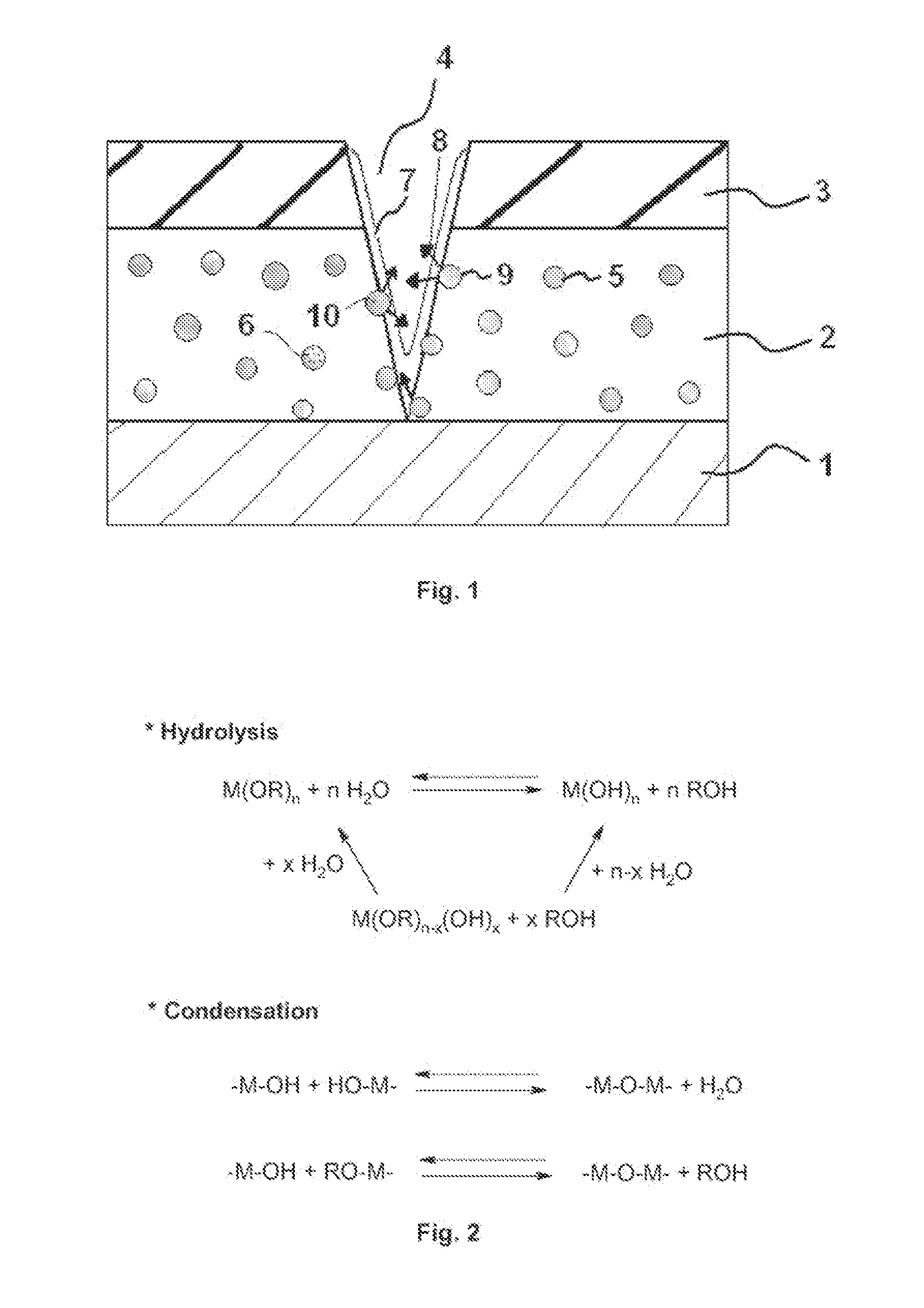
[0024]It has also been made possible to trigger the release of corrosion inhibitors by the presence of water. As said presence of water is one of the corrosion conditions, the corrosion inhibitors are advantageously released when they are needed. The ceramic particles are able to provide long-lasting release of the corrosion inhibitors. Therefore, the present invention provides coating compositions with self-healing properties.
[0027]This homogeneous distribution results in a relatively stable release profile of the inhibitors, even after a formulation step involving grinding. On the contrary, capsules or other core shell particles such as described in the anterior art release their content instantly when the shell is ruptured.

Problems solved by technology

The corrosion of the alloy may cause important damages to the aircraft structure.
However, only the combination of both these strategies can give reliable long-term corrosion protection of metallic structures, which are in constant contact with electrolytes or a humid environment.
However, these strong oxidation properties also make hexavalent chromium environmentally unsafe.
This compound is especially known to be carcinogenic.
However, especially in sol-gel coatings, the direct addition of high levels of corrosion inhibitor in a coating composition often results in detrimental properties of the resulting coating.
However, a difficulty lies in controlling the release of the corrosion inhibitor, in order to have a sufficient amount of available inhibitor when the coated metallic device is placed in corrosive conditions.
However, the surface anchoring of the particles described in U.S. Pat. No. 6,933,046 is limited to rather low levels of inhibitors.
In addition, anchoring organic inhibitors on particle surfaces leads to more hydrophobic particle surfaces, which can be detrimental to the coating structure, similarly as directly adding organic inhibitors into coatings.
Moreover, some free inhibitors always remain at the surface of the particles after post-loading, which leads to interaction with the coating.
The above mentioned particles do not display such mechanical properties and are therefore unsuitable to be incorporated in these compositions.

Method used


Image

  • Ceramic particles and coating compositions including said particles
  • Ceramic particles and coating compositions including said particles

Examples


example i

Synthesis of an Organic-Inorganic Sol-Gel Matrix

[0090]48 g of glacial acetic acid were added under stirring to zirconium (IV) propoxide solution (105 g, 70% in 1-propanol). After slow addition of deionised water (602 g), the solution was stirred until homogeneous (1 hour). 245 g of 3-glycidoxypropyltrimethoxysilane (GPTMS) were then added and the solution was stirred for another hour. The resulting solution is called the sol-gel matrix solution in the following examples and is used as a representative coating solution.

example ii

Synthesis of the Sol-Gel Particles Containing Corrosion Inhibitors

example ii.1

Inorganic Inhibitor Encapsulation

[0091]A surfactant solution was prepared by mixing a surfactant NP-5 (160 mmol) and cyclohexane (800 mL). 17.28 mL of a solution of Ce(NO3)3 in water (80 mg / mL of Ce3+) was added into the surfactant solution, which was then stirred for 30 minutes to form a transparent water-in-oil microemulsion. Tetramethyl orthosilicate (TMOS, 144 mmol) was added to the above microemulsion which was then stirred for 10 minutes, before the addition of (3-Aminopropyl)triethoxysilane (APTES, 3.6 mmol). The synthesis was aged overnight (16-24 hours) at 30° C. After decreasing the temperature to 20° C., 960 mL of acetone was added into the mixture and stirred for 30 minutes to destabilise the emulsion. The mixture was then centrifuged for 25 minutes at 5000 rpm. The supernatant was decanted and the particles were collected. The particles were then either freeze-dried or suspended in a concentrated slurry, as required for the following step.


PUM

PropertyMeasurementUnit
Fractionaaaaaaaaaa
Fractionaaaaaaaaaa
Corrosion propertiesaaaaaaaaaa

Abstract

The present invention relates to coating compositions for metallic devices, especially for aircrafts, to provide protection against corrosion. The coating composition comprises ceramic particles having at least one active material substantially homogeneously distributed throughout each particle. The active material being releasable in the presence of a liquid by solubilization into the liquid.

Description

TECHNICAL FIELD OF INVENTION[0001]The present invention relates to coating compositions, especially for metallic devices. The present invention more specifically relates to coating compositions for aircrafts.BACKGROUND OF THE INVENTION[0002]The structure of an aircraft is commonly metallic, especially composed of aluminium alloys. A modern aircraft coating system combines the need to provide protection against corrosion and the environment, decoration or camouflage and a good mechanical adhesion. One of the typical coating systems is composed of three individual layers.[0003]A bottom layer may be an anodizing layer or a conversion coating. This bottom layer is typically formulated using an inorganic matrix. It provides corrosion protection and improves adhesion between a metallic substrate, which is the aircraft structure, and a middle layer.[0004]A middle layer, also called primer, typically includes a pigmented organic resin matrix. The primer is usually the principal provider of ...

Claims


Application Information

Patent Timeline
IPC IPC(8): C09D5/08C09D163/00
CPCC09D5/082C23C22/74Y02T50/67C23F11/185C23F11/10Y02T50/60
Inventor BARBE, CHRISTOPHECALDEIRA, NANCY MANUELACAMPAZZI, ELISAKONG, LINGGENFINNIE, KIM SUZANNEVILLATTE, MARTINE
Owner CERAMISPHERE
Learn More