
Nanocomposite thermoelectric conversion material and method of producing the same

a thermoelectric conversion material and nanocomposite technology, applied in the manufacture/treatment of thermoelectric devices, non-metal conductors, conductors, etc., can solve the problems of inability to prevent the precipitation of phonon-scattering particles, the amount of salt of metal or alloy in the solution is excessive with respect, and the smallest dispersed ceramic particles are sub-micron particles. , to achieve the effect of reducing thermal conductivity and high phonon-scattering

Active Publication Date: 2012-04-12
TOYOTA JIDOSHA KK
View PDF3 Cites 6 Cited by
  • Summary
  • Abstract
  • Description
  • Claims
  • Application Information

AI Technical Summary

Benefits of technology

[0014]The invention provides a nanocomposite thermoelectric conversion material in which nano-sized phonon-scattering particles are dispersed in a matrix made of a thermoelectric conversion material, and which has a greatly decreased thermal conductivity, and significantly improved thermoelectric conversion performance, and a method of producing the same.
[0018]According to the above-described aspects, the elements constituting the thermoelectric conversion material of the matrix are precipitated first, and particles including the elements are produced. Then, the phonon-scattering particles are precipitated among the particles including the elements constituting the matrix. Therefore, the phonon-scattering particles are not agglutinated, and the nano-size of the phonon-scattering particles is maintained. Therefore, it is possible to obtain the extremely high phonon-scattering effect. As a result, it is possible to produce the nanocomposite thermoelectric conversion material with the significantly decreased thermal conductivity.

Problems solved by technology

In this method, however, even the smallest dispersed ceramic particles are sub-micron sized particles.
The amount of the salt of the metal or the alloy contained in the solution is excessive with respect to the amount of the metal or the alloy to be contained in the thermoelectric conversion material.
Therefore, it is not possible to prevent the agglutination of the precipitated phonon-scattering particles, and the increase in the size of the phonon-scattering particles.

Method used


Image

  • Nanocomposite thermoelectric conversion material and method of producing the same
  • Nanocomposite thermoelectric conversion material and method of producing the same
  • Nanocomposite thermoelectric conversion material and method of producing the same

Examples


first embodiment

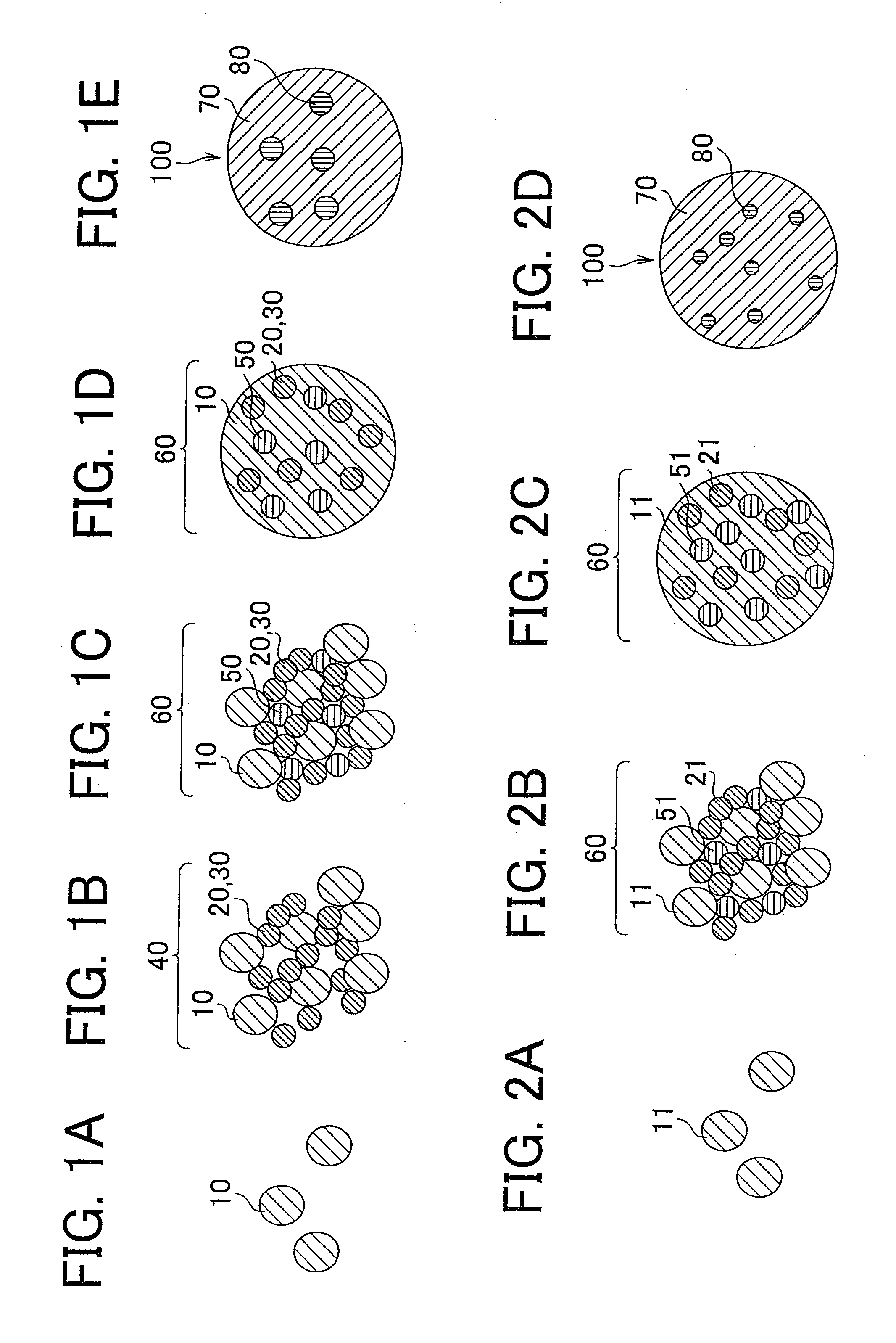
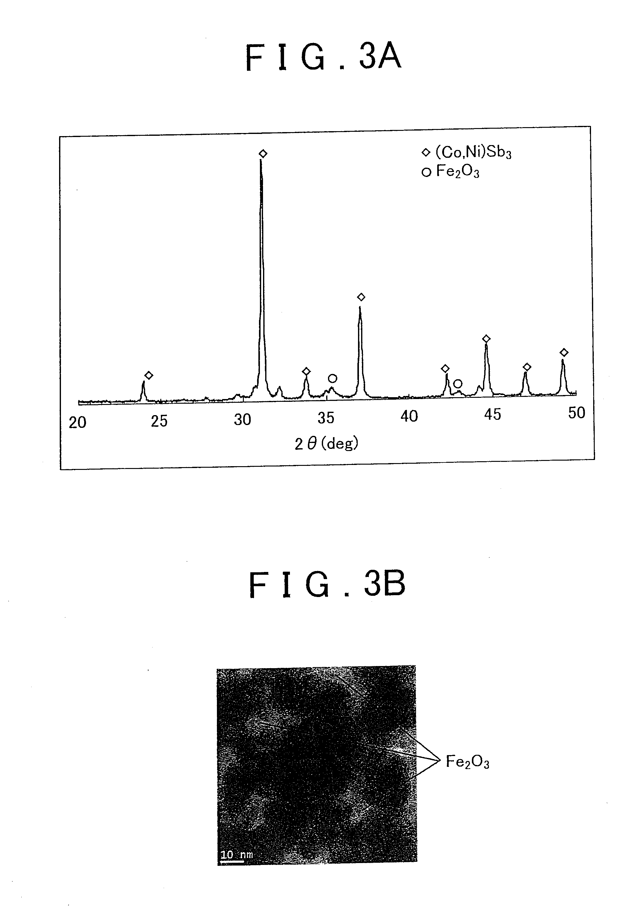
[0027]FIGS. 1A to 1E schematically show processes according to a first embodiment of the invention. The description will be made on the assumption that a nanocomposite thermoelectric conversion material, in which particles made of Fe2O3 are dispersed in a matrix made of a thermoelectric conversion material (Co, Ni) Sb3, is produced. The particles made of Fe2O3 serve as particles used for scattering phonons (hereinafter, referred to as “phonon-scattering particles”).

First Step

[0028]A solution, which contains salts of a plurality of first elements Co, Ni, and Sb that constitute the thermoelectric conversion material (Co, Ni) Sb3, and a salt of a second element Fe that has a redox potential lower than redox potentials of the first elements, is prepared.

[0029]The redox potentials of the elements in decreasing order are as follows. The redox potential of Sb is 0.16V. The redox potential of Ni is −0.25 V. The redox potential of Co is −0.27V. The redox potential of Fe is −0.44V.

Second Step...

second embodiment

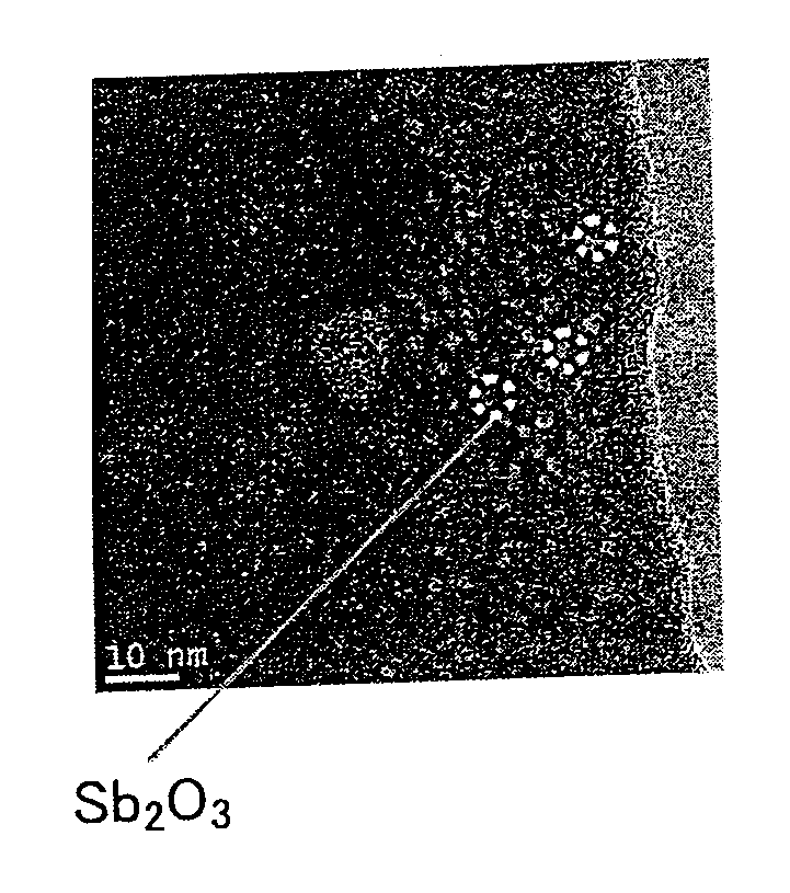
[0038]FIGS. 2A to 2D schematically show processes according to a second embodiment of the invention. The description will be made on the assumption that a nanocomposite thermoelectric conversion material, in which particles made of Sb2O3 are dispersed in a matrix made of a thermoelectric conversion material (Bi, Sb)2Te3, is produced. The particles made of Sb2O3 serve as phonon-scattering particles.

First Step

[0039]A solution, which contains salts of a plurality of first elements Bi, Sb, and Te that constitute the thermoelectric conversion material (Bi, Sb)2Te3, is prepared. The solution contains an excessive amount of the salt of a predetermined element (Sb) among the plurality of the first elements, with respect to a predetermined composition of the thermoelectric conversion material, and the redox potential of the predetermined element (Sb) is not the highest among the redox potentials of the first elements (Te has the highest redox potential).

[0040]In this case, the redox potentia...

first example

[0047]The nanocomposite thermoelectric conversion material, in which 10 vol % of Fe2O3 particles were dispersed in the matrix made of the thermoelectric conversion material (Co, Ni) Sb3, was produced according to a procedure described below on a condition described below, using the method according to the first embodiment of the invention. The Fe2O3 particles served as phonon-scattering particles.

Preparation of a Source Material Solution

[0048]A source material solution was prepared by dissolving source materials described below, in 100 ml of ethanol.

[0049]The source materials for the matrix were 2.75 g of antimony chloride (SbCl3), 0.9 g of cobalt chloride hexahydrate (CoCl2·6H2O), and 0.057 g of nickel chloride hexahydrate (NiCl2·6H2O). The source material for the dispersed particles was 0.335 g of ferric chloride hexahydrate (FeCl3·6H2O).

Reduction

[0050]A solution, which was produced by dissolving 2.4 g of NaBH4, which served as a reducing agent, in 100 ml of ethanol, was dropped i...


PUM

PropertyMeasurementUnit
thermal conductivityaaaaaaaaaa
particle diameteraaaaaaaaaa

Abstract

A method of producing a nanocomposite thermoelectric conversion material includes preparing a solution that contains salts of a plurality of first elements constituting a thermoelectric conversion material, and a salt of a second element that has a redox potential lower than redox potentials of the first elements; precipitating the first elements, thereby producing a matrix-precursor that is a precursor of a matrix made of the thermoelectric conversion material, by adding a reducing agent to the solution; precipitating the second element in the matrix-precursor, thereby producing slurry containing the first elements and the second element, by further adding the reducing agent to the solution; and alloying the plurality of the first elements, thereby producing the matrix (70) made of the thermoelectric conversion material, and producing nano-sized phonon-scattering particles (80) including the second element, which are dispersed in the matrix (70), by filtering and washing the slurry, and then, heat-treating the slurry.

Description

BACKGROUND OF THE INVENTION[0001]1. Field of the Invention[0002]The invention relates to a method of producing a nanocomposite thermoelectric conversion material in which nano-sized phonon-scattering particles are dispersed in a matrix made of a thermoelectric conversion material, and a nanocomposite thermoelectric conversion material produced using the method.[0003]2. Description of the Related Art[0004]A thermoelectric conversion material is an energy material that directly converts thermal energy to electric energy, based on two basic thermoelectric effects, that is, the Seebeck effect and the Peltier effect.[0005]A thermoelectric generation device, which uses the thermoelectric conversion material, has many advantages as compared to conventional power generation technologies. For example, the thermoelectric generation device has a simple structure, and is robust and highly durable. The thermoelectric generation device does not have a movable member. The micro-sized thermoelectri...

Claims


Application Information

Patent Timeline
Patent Type & Authority Applications(United States)
IPC IPC(8): H01B1/02H01B1/00B82Y30/00
CPCB22F9/24B22F2998/10C22C1/0491C22C32/0015H01L35/16H01L35/26Y10T428/29H01L35/34Y10S977/779B22F1/0022B22F1/0085C22C1/047H10N10/857H10N10/852H10N10/01
Inventor MURAI, JUNYAKITA, TAKUJI
Owner TOYOTA JIDOSHA KK
Learn More