
System and Method for Pulse-Echo Ranging

Active Publication Date: 2012-04-19
SIEMENS AG
View PDF7 Cites 6 Cited by
  • Summary
  • Abstract
  • Description
  • Claims
  • Application Information

AI Technical Summary

Benefits of technology

[0012]It is therefore an object of the invention to provide a system and method that overcome the prior art drawbacks and compensates for phase error and thermal drift between the transmit and sampling instants.
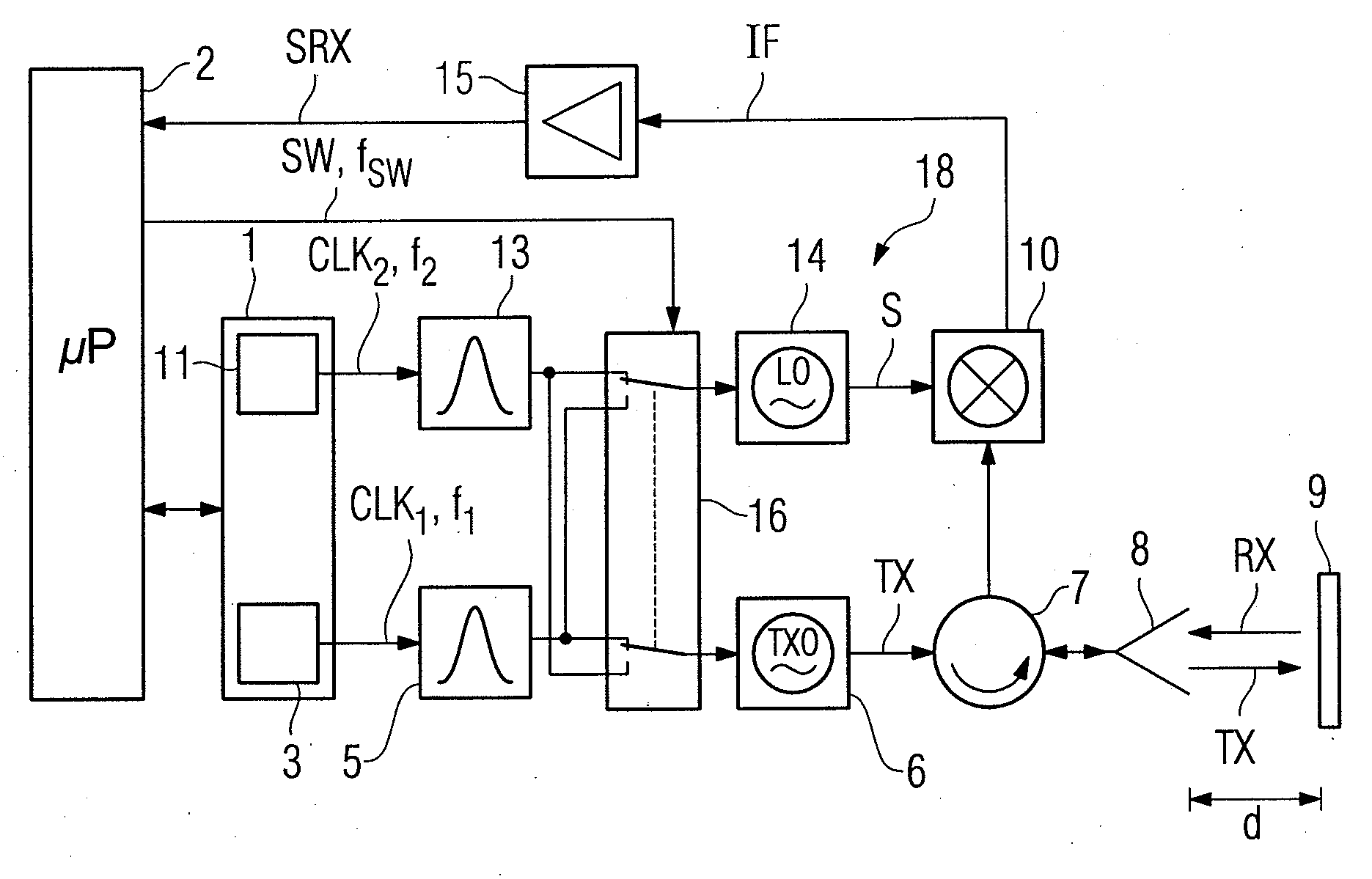
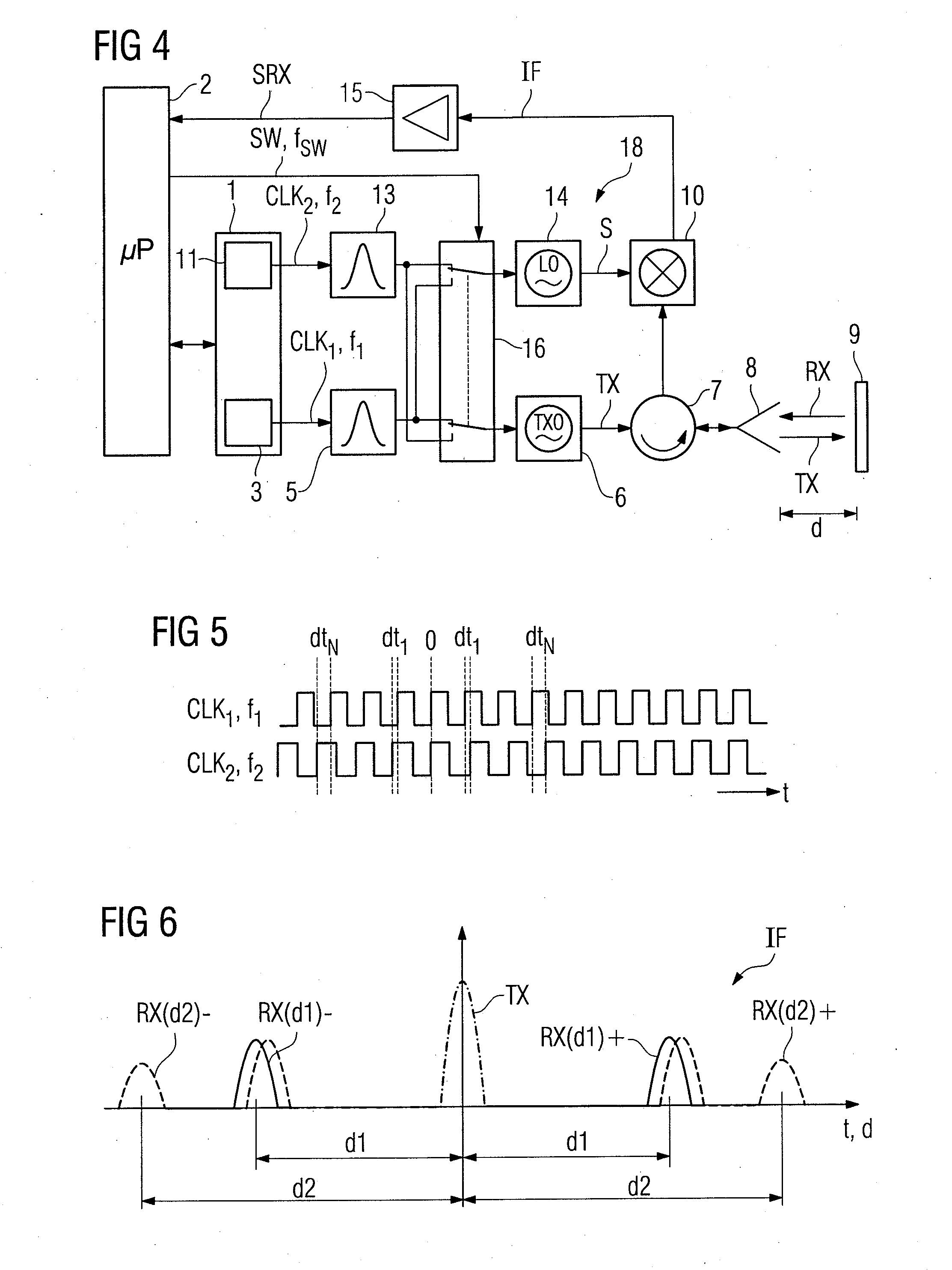
[0016]In accordance with an embodiment of the invention, the transmit and sampling clock frequencies are periodically switched between the first clock frequency and the slightly lower second clock frequency. As a result, the echo pulses are alternately sampled in the forward-in-time direction and a backward-in-time direction, which provides both time-expanded echoes having a positive time delay and time-expanded echoes having a negative time delay with respect to the coincidence moment. Here, the positive and negative time delay are equal. As a result, the time of flight or physical distance to the target is half of the distance between the positively and negatively delayed echoes so that no coincidence (i.e., zero phase) detection is necessary.
[0017]In addition, any difference in delay or drift of the first and second clocks in the signal paths between the clock generators and the switching device is eliminated because the drift will affect both the transmit pulses and the sampling pulses. Therefore, the distance between the positively and negatively delayed echoes will remain constant.
[0018]As is known from the above-mentioned U.S. Pat. No. 7,633,434 B2, the received echo pulses may be sampled by cross-correlation, for which purpose the receiving device may comprise a further burst generator triggered by the second clock for generating sampling pulses and a signal mixer for generating the intermediate frequency signal by mixing the echo pulses with the sampling pulses. In principle, it is possible to directly trigger the burst generators by the first and second clocks to generate rectangular transmit and sampling pulses. However, a smoother pulse shape is usually preferred. As a result, the rectangular clocks may be fed by pulse shapers to the burst generators. In this case, and in accordance with a preferred embodiment of the invention, the pulse shapers are arranged between the respective clock generators and the switching device so that any thermal drift introduced by the variation of the delay of the pulse shapers is eliminated.

Problems solved by technology

However, during start up of the crystal oscillators, the phase difference between the clock signals is not predictable.
Zero phase detector errors may diminish the merits of the digital solution and the measurement time is increased because a waiting time for zero phase detection has to be added.
Consequently, there may be a significant measurement drift created by different variations over temperature of the propagation delay in the transmit and sampling pulse shapers.
However, this known solution is complex and the additional microwave switch affects the measurement signal.

Method used


Image

  • System and Method for Pulse-Echo Ranging
  • System and Method for Pulse-Echo Ranging
  • System and Method for Pulse-Echo Ranging

Examples


Embodiment Construction

[0030]In the figures, like reference numbers indicate similar elements or signals.

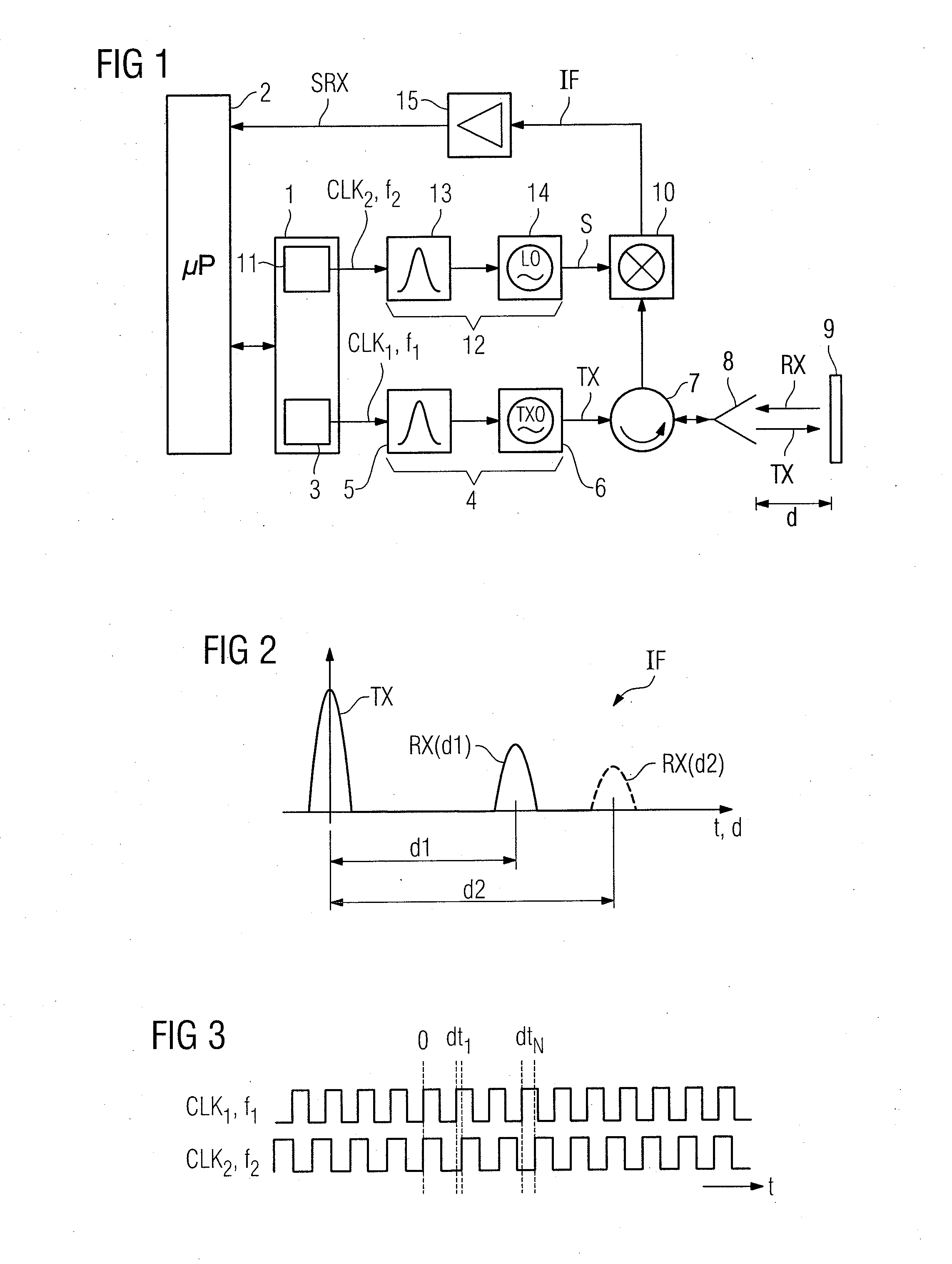
[0031]With specific reference to FIG. 1, which shows basic components of a prior art pulse-echo radar ranging system, a time base control circuit 1, which is under control of a microcontroller 2, contains a transmit clock generator 3 for generating a transmit clock CLK1 at a transmit clock frequency f1 in the MHz range. The transmit clock CLK1 triggers a transmit pulse generator 4 comprising a pulse shaper 5 and a first microwave oscillator 6 for generating microwave transmit pulses TX with a pulse repetition rate equal to the transmit clock frequency f1. The transmit pulses TX may be obtained by modulating the microwave oscillator 6 or gating continuous oscillation of the microwave oscillator 6 and may have a duration of 1 ns and a frequency in the GHz range. The transmit pulses TX are transmitted through a directional coupler (hybrid) 7 and an antenna 8 to a target 9, such as the surface of a fill ma...


PUM


Abstract

A pulse-echo ranging system and method wherein transmit burst pulses are transmitted to a target at a first repetition frequency, an intermediate frequency signal is generated by sampling the received echo pulses from the target at a second repetition frequency slightly lower than the first repetition frequency, and the intermediate frequency signal is evaluated to determine the target distance. In order to compensate for phase error and thermal drift which may occur when the transmit and sampling instants are generated, the transmit burst pulses are periodically and alternately transmitted at the first and second repetition frequencies while the received echo pulses are simultaneously sampled at the second and first repetition frequencies, and the target distance is determined as half of the distance between echoes appearing in the intermediate frequency signal and resulting from the different clocks.

Description

BACKGROUND OF THE INVENTION[0001]1. Field of the Invention[0002]The present invention relates pulse-echo ranging and more particularly, to a pulse-echo ranging system comprising a first clock generator for generating a first clock at a first clock frequency, a second clock generator for generating a second clock at a second clock frequency slightly lower than the first clock frequency, a burst generator triggered by the first clock for generating burst pulses at the first clock frequency and for conveying the burst pulses to be transmitted to a target, a receiving device triggered by the second clock for generating an intermediate frequency signal by sampling echo pulses reflected from the target at the second clock frequency, and a signal processing device configured to evaluate the intermediate frequency signal to determine the target distance.[0003]The invention further relates to a pulse-echo ranging method comprising transmitting transmit burst pulses to a target at a first rep...

Claims


Application Information

Patent Timeline
IPC IPC(8): G06F15/00G01B21/16
CPCG01S7/282G01S13/103G01S7/285
Inventor BURCEA, GEORGE
Owner SIEMENS AG
Learn More