
Conducting formulation

a technology of conducting formulation and formulation, applied in the direction of non-metal conductors, triarylamine dyes, conductors, etc., can solve the problems of static charge buildup, fire or explosion, electrostatic discharge, etc., and achieve the effect of increasing the conductivity of the formulation

Inactive Publication Date: 2012-05-03
MERCK PATENT GMBH
View PDF5 Cites 5 Cited by
  • Summary
  • Abstract
  • Description
  • Claims
  • Application Information

AI Technical Summary

Benefits of technology

[0009]Surprisingly it has been found that these aims can be achieved, and the above-mentioned problems can be solved, by providing methods, materials and devices as claimed in the present invention, especially by providing a process for preparing an OLED device using a low conducting ink based on a non-conducting solvent. In particular, it has been found that it is possible to provide an ink with a low conductivity, which is sufficiently high to avoid the building of static charge in the printing process used for depositing the light emitting materials and / or charge transporting materials onto the OLED device, but is also sufficiently low to avoid a significant negative influence on the OLED device performance. This is achieved by providing an ink comprising at least one light emitting material and / or charge transporting material and at least one non-conducting organic solvent, preferably an aromatic solvent, and further comprising a small amount of one or more conductivity enhancing agents, i.e. additives that increase the conductivity of the formulation (hereinafter also shortly referred to as “conductive additives”). The conductive additive(s) used is either volatile, so that it is evaporated together with the solvent after deposition of the layer, containing the light emitting materials and / or charge transporting materials, on the device, and is thus not remaining in the OLED device. Alternatively the conductive additive used does not have an oxidising effect on the light emitting materials and / or charge transporting materials. As a result, permanent electrical doping of the light emitting materials and / or charge transporting materials, which could render the light emitting materials and / or charge transporting materials too conductive and thereby adversely affect the desired OLED device properties, is avoided.

Problems solved by technology

However, high speed coating of a substrate with an ink or fluid, containing light emitting materials and / or charge transporting materials, can lead to a build up of static charge if the fluid is not conducting.
This can lead to an electrostatic discharge by arcing, and, if the solvent is flammable, result in a fire or explosion.
However, the rapid pumping of a non-conductive flammable fluid to a coating or printing head can also lead to electrostatic discharge.
However, this can put serious restraints on the possible choice of solvents for the fluid, containing light emitting materials and / or charge transporting materials.
However, these solvents are virtually non-conductive and will therefore imply the above-mentioned problems due to static charge.
However, when using a fluid comprising standard light emitting materials and / or charge transporting materials, like conjugated polymers in an aromatic hydrocarbon solvent, it was so far not possible to achieve the required conductivity without permanently doping the polymer (for example with iodine or other oxidants).
For the uses of the present invention, however, permanent doping is undesired as it would lead to a deterioration of the OLED device performance.
In particular, it has been found that it is possible to provide an ink with a low conductivity, which is sufficiently high to avoid the building of static charge in the printing process used for depositing the light emitting materials and / or charge transporting materials onto the OLED device, but is also sufficiently low to avoid a significant negative influence on the OLED device performance.

Method used


Image

  • Conducting formulation
  • Conducting formulation
  • Conducting formulation

Examples


working examples

[0086]The following materials were used in the working examples:

[0087]3,4-Dimethylanisole, tetraoctylammonium bromide and trifluoroacetic acid were purchased from Sigma-Aldrich.

[0088]Triethylamine was purchased from VWR.

[0089]Tributylammonium trifluoroacetate was obtained by adding a 1:1 molar ratio of tributylamine and trifluoroacetic acid to the solution. First tributylamine was added to the solution followed by trifluoroacetic acid.

[0090]Triethylammonium trifluoroacetate was obtained by adding a 1:1 molar ratio of triethylamine and trifluoroacetic acid using the method above.

[0091]Conductivity (C) was obtained from calculated resistivity p using the following equations:

C=1ρ[S / m],whereρ=RAl=R×1k=Rk[Ωm],

and the cell constant k=I / A was determined from the cell dimensions, where I was the distance between the electrodes and A was the area of electrodes and R=V / I [Ω].

[0092]Measurements were performed by placing each solution into a cylindrical measurement cell of known dimensions. The...

example 1

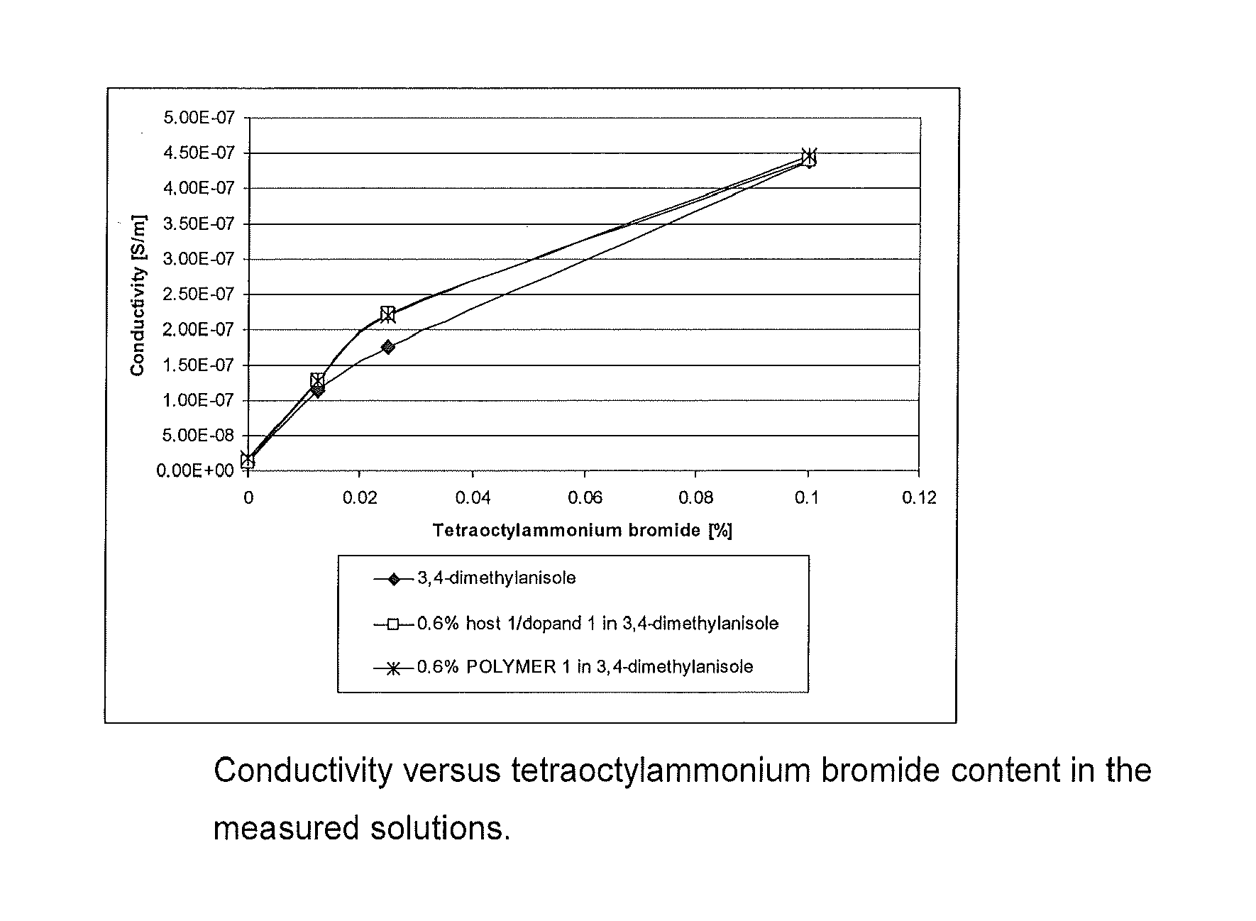
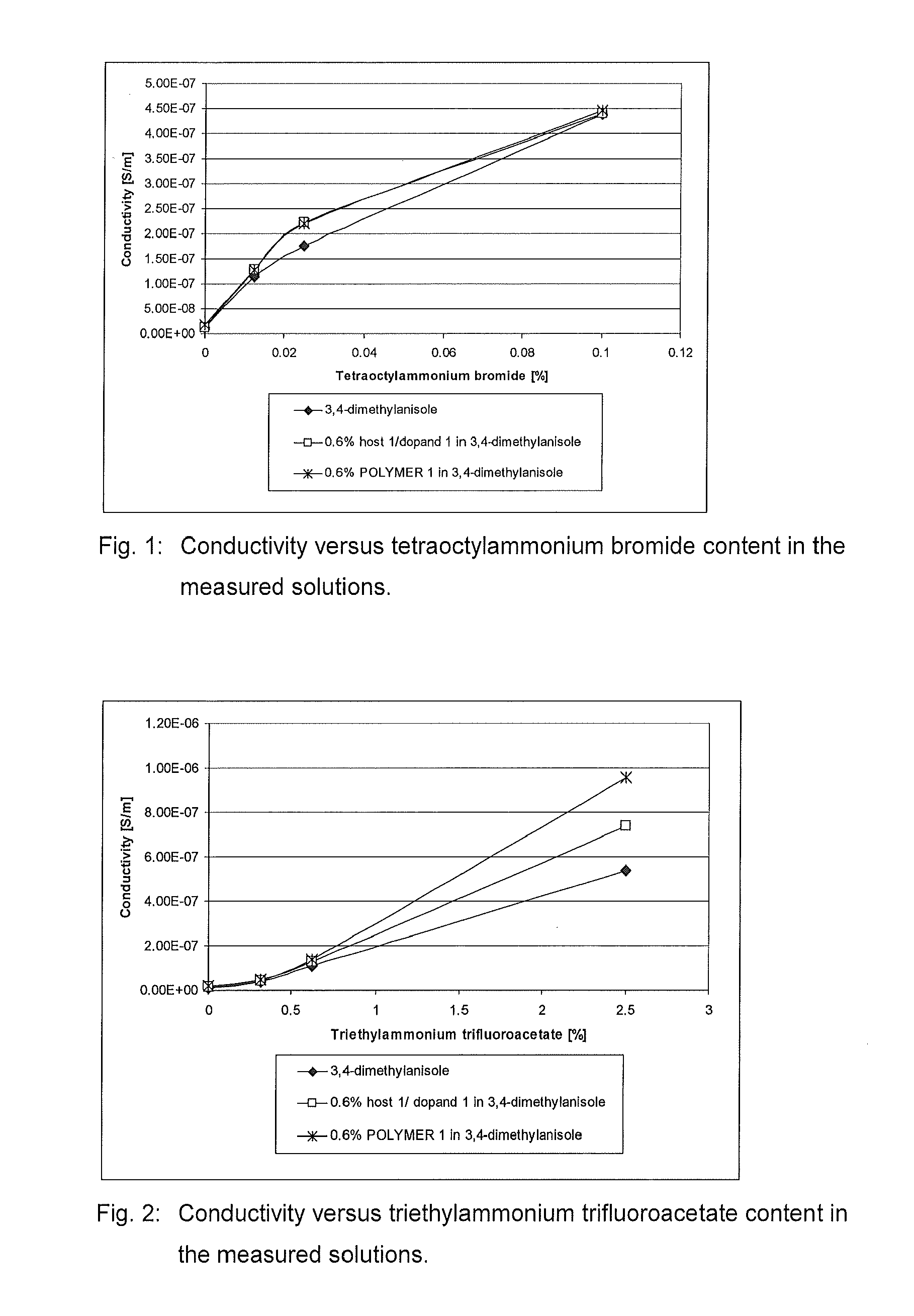
[0094]The resistance of o-xylene, tetraoctylammonium bromide in o-xylene, tributylammonium trifluoroacetate in o-xylene, 3,4-dimethylanisole, tetraoctylammonium bromide in 3,4-dimethylanisole and triethyl-ammonium trifluoroacetate in 3,4-dimethylanisole were measured and the conductivities were calculated. The results are presented in Table 1 and displayed as a function of the concentration in FIGS. 1 and 2.

TABLE 1LiquidAdditive and its concentrationconductivitySolvent[wt. %][S / m]air0 (control)1.19 × 10⁻¹²o-xylene0 (control)1.55 × 10⁻⁹o-xylenetetraoctylammonium bromide,2.70 × 10−80.025o-xylenetributylammonium4.73 × 10−8trifluoroacetate, 1.03,4-dimethylanisole0 (control)1.14 × 10−83,4-dimethylanisoletetraoctylammonium bromide,1.07 × 10−70.01253,4-dimethylanisoletetraoctylammonium bromide,1.76 × 10−70.0253,4-dimethylanisoletetraoctylammonium bromide,4.38 × 10−70.13,4-dimethylanisoletriethylammonium4.00 × 10−8trifluoroacetate, 0.31253,4-dimethylanisoletriethylammonium1.10 × 10−7trifluo...

example 2

[0096]

[0097]0.6 parts of Polymer 1 (c.f. Example 6 in EP 1741148) were dissolved in 99.4 parts of 3,4-dimethylanisole (0.6% of Polymer 1 in 3,4-dimethylanisole).

[0098]The resistance of Polymer 1 solution, tetraoctylammonium bromide in Polymer 1 solution and triethylammonium trifluoroacetate in Polymer 1 solution were measured and the conductivities were calculated as described in Example 1. The results are presented in Table 2 and displayed as a function of the concentration in FIGS. 1 and 2.

TABLE 2LiquidAdditive and its concentrationconductivitySolution[wt. %][S / m]0.6% w / w POLYMER 10 (control)1.86 × 10⁻⁸in 3,4-dimethylanisole0.6% w / w POLYMER 1tetraoctylammonium bromide,1.29 × 10−7in 3,4-dimethylanisole0.01250.6% w / w POLYMER 1tetraoctylammonium bromide,2.20 × 10−7in 3,4-dimethylanisole0.0250.6% w / w POLYMER 1tetraoctylammonium bromide,4.47 × 10−7in 3,4-dimethylanisole0.10.6% w / w POLYMER 1triethylammonium4.85 × 10−8in 3,4-dimethylanisoletrifluoroacetate, 0.31250.6% w / w POLYMER 1trieth...


PUM


Abstract

The present invention relates to novel formulations comprising light emitting materials and / or charge transporting materials and a conductive additive, to their use as conducting inks for the preparation of organic light emitting diode (OLED) devices, to methods for preparing OLED devices using the novel formulations, and to OLED devices prepared from such methods and formulations.

Description

FIELD OF THE INVENTION[0001]The present invention relates to novel formulations comprising light emitting materials and / or charge transporting materials and a conductive additive, to their use as conducting inks for the preparation of organic light emitting diode (OLED) devices, to methods for preparing OLED devices using the novel formulations, and to OLED devices prepared from such methods and formulations.BACKGROUND AND PRIOR ART[0002]When preparing OLED devices, usually printing techniques like inkjet printing, roll to roll printing, slot dye coating, flexographic or gravure printing are used to apply the active layer. Contact printing techniques like gravure printing operate at high speed. However, high speed coating of a substrate with an ink or fluid, containing light emitting materials and / or charge transporting materials, can lead to a build up of static charge if the fluid is not conducting. This can lead to an electrostatic discharge by arcing, and, if the solvent is flam...

Claims


Application Information

Patent Timeline
IPC IPC(8): H01L51/54H01B1/12H01L51/56
CPCC09D5/24C09D11/52C09K11/06C09K2211/185H01L51/0085C09B57/10H01L51/5012H05B33/14C09B57/00C09B57/008H01L51/0087H10K85/342H10K85/346H10K50/11
Inventor JAMES, MARKGONCALVES-MISKIEWICZ, MAGDAEFFENBERGER, RUTHBONRAD, KLAUS
Owner MERCK PATENT GMBH
Learn More