Electric driving range calculator

a calculator and driving range technology, applied in the direction of batteries/cells, instruments, process and machine control, etc., can solve the problems of complex methodologies, inability of vehicular operators to correlate driving distance with available battery charge, and complex methodologies that require extensive training of engineers, researchers, computer programmers, etc., and achieve the effect of convenient integration

Active Publication Date: 2012-05-03
GM GLOBAL TECH OPERATIONS LLC
View PDF19 Cites 33 Cited by
  • Summary
  • Abstract
  • Description
  • Claims
  • Application Information

AI Technical Summary

Benefits of technology

[0005]Embodiments of the present invention can be used to calculate driving range of an EREV or other RESS-based vehicular propulsion system without the need to resort to complex models such as those discussed above. More particularly, the calculation may be based on simple inputs of driving parameters, such as trip distance, a typical time to complete such trip and particular geographic location, climate or the like. Features of the present invention could be made into an application that could be easily integrated with a smart phone, global positioning system (GPS) device or directly integrated into the vehicle's driver information center or related onboard computer-based device. One objective of the present invention is to be able to provide an electric driving distance output that is accurate to within about 1.5 miles.

Problems solved by technology

Irrespective of the battery form, it would be inconvenient for a vehicular operator to correlate driving distance with available battery charge.
Methods to perform this correlation are available, but they require detailed information about (among other things) a particular operator's driving behavior and geographic location, thereby making such a system impractical.
For example, modeling simulation tools allow for output of vehicle energy-related metrics (including acceleration, fuel economy, driving distance or the like), but involve complex methodologies that require extensive training of engineers, researchers, computer programmers or related highly-skilled personnel in order to use such models successfully.
Moreover, such models require large amounts of input data in order to be run correctly.
Furthermore, such models also require high-powered computers to run the complex software.

Method used


Image

  • Electric driving range calculator
  • Electric driving range calculator
  • Electric driving range calculator

Examples


Embodiment Construction

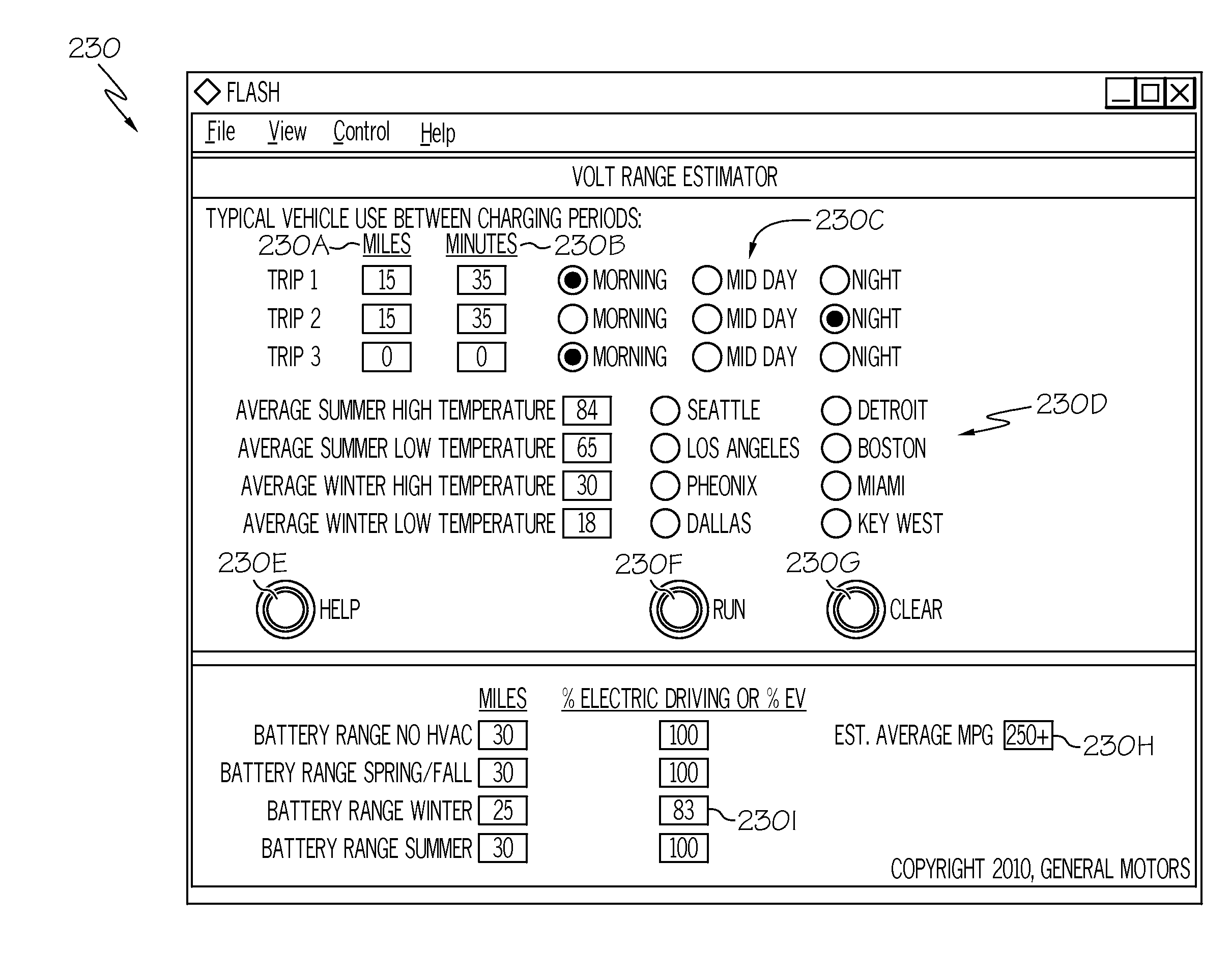
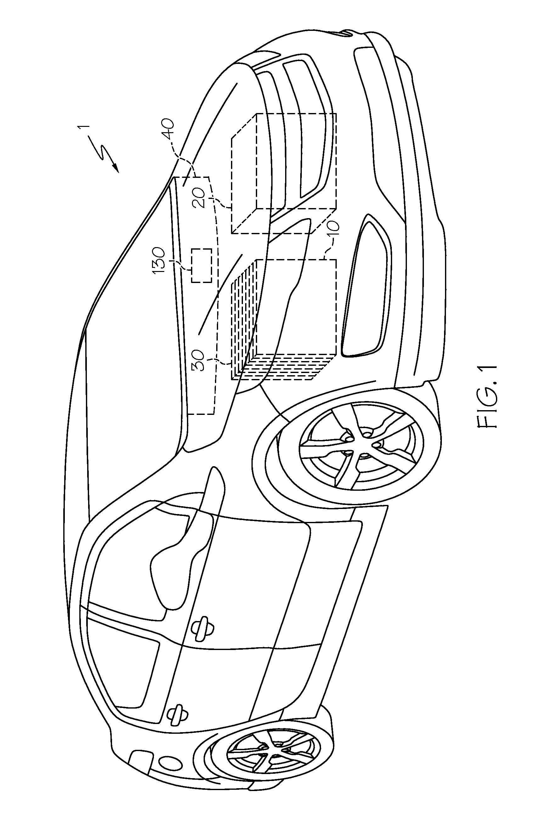
[0019]Referring first to FIG. 1, a vehicle 1 includes a hybrid propulsion system in the form of a battery pack 10 and a conventional ICE 20. As mentioned above, such a vehicle is known as an EREV. Battery pack 10 employs numerous battery modules 30 that are typically arranged in a repeating array as shown. In one typical example, battery pack 10 may about two hundred individual battery cells, although it will be appreciated by those skilled in the art that additional or fewer cells may be needed, depending on the power required. It will be further appreciated by those skilled in the art that vehicle 1 may not require an ICE 20; in such case, rather than being an EREV, it is an EV; either form is equally compatible with the present invention. The vehicle 1 is shown as having a dashboard 40 with a display screen (or more simply, display) 130 as a way to provide informational output, as will be discussed in more detail below.

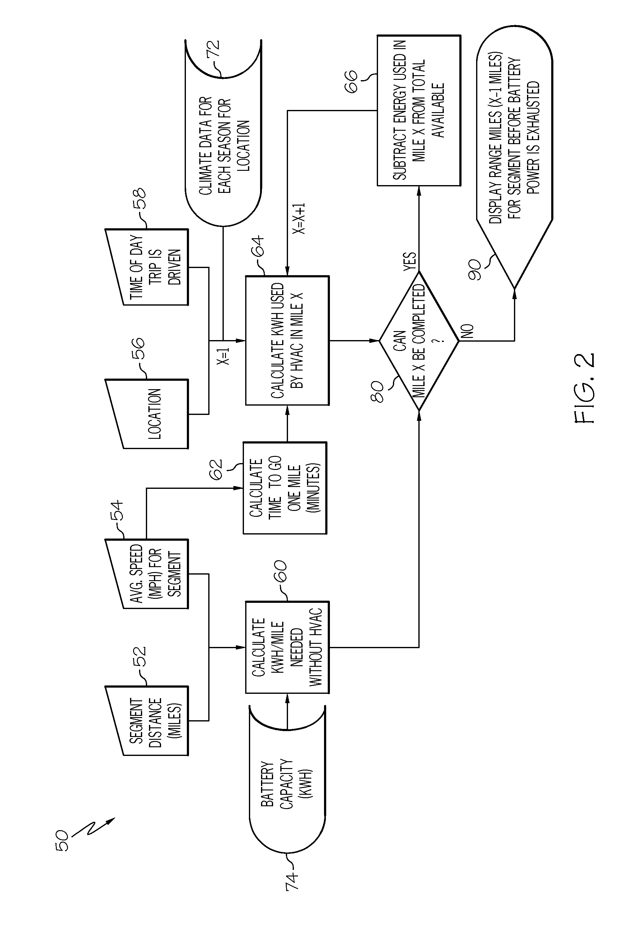
[0020]Referring next to FIG. 2, steps in using the empirical ...


PUM


Abstract

A method of and device for determining driving range for a vehicle operating with a rechargeable energy storage supply. The method includes performing a calculation based on a limited number of input parameters, including a driving distance, average speed, location and time of day. Other determinations, such as the possibility of using a battery power-depleting climate control system, as well as battery capacity and climate data for various seasonal and location factors may also be used in the calculations.

Description

[0001]This application claims the benefit of the filing date of U.S. Provisional Application No. 61 / 408,152, filed Oct. 29, 2010.BACKGROUND OF THE INVENTION[0002]This invention relates generally to a method and device to calculate the driving range for a vehicle, and more particularly to calculating the driving range for such a vehicle that is operating in an electric-only (i.e., charge-depleting) mode of a propulsion system that is relying at least in part on a battery-based power supply.[0003]Hybrid and electric vehicles provide an alternative to conventional means of vehicular motive power by either supplementing (in the case of hybrids) or completely replacing (in the case of electric vehicles) a vehicle's traditional internal combustion engine (ICE). One form of such alternative vehicle is known as an extended range electric vehicle (EREV). In one embodiment of the EREV, primary electric drive is achieved with a battery or related rechargeable energy storage system (RESS) that ...

Claims


Application Information

Patent Timeline
Patent Type & Authority Applications(United States)
IPC IPC(8): G06F7/00
CPCB60L11/1877Y02T10/7005Y02T10/705B60L2200/26B60L2240/12B60L2250/16B60L50/66B60L2260/54B60W40/10B60W2510/244B60W2510/305B60W2550/402Y02T10/84B60L2260/52B60W2556/50Y02T10/70
Inventor SMITH, IRVIN T.BARTNICK, BRIAN K.LAWS, LARRY D.PEREKATTU, GEORGE K.
Owner GM GLOBAL TECH OPERATIONS LLC
Why Eureka
Try Eureka