Mass spectrometer
a mass spectrometer and mass spectrometer technology, applied in the field of mass spectrometers, can solve the problem of greater loss of ionized measurement samples during their transport than, and achieve the effect of reducing size and weight and high-precision mass spectroscopy
- Summary
- Abstract
- Description
- Claims
- Application Information
AI Technical Summary
Benefits of technology
Problems solved by technology
Method used
Image
Examples
first embodiment
Variation of First Embodiment
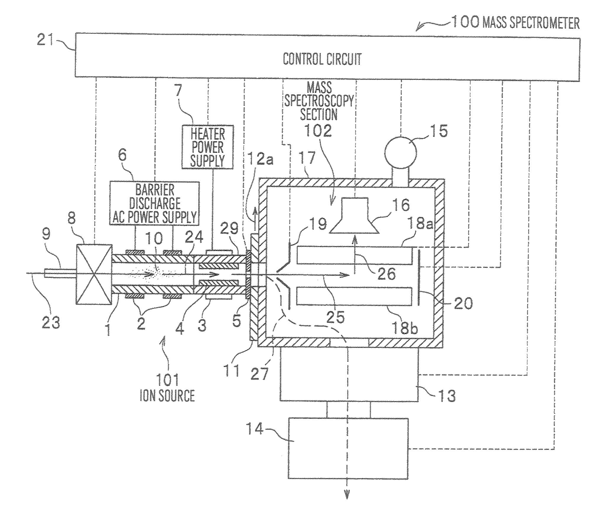
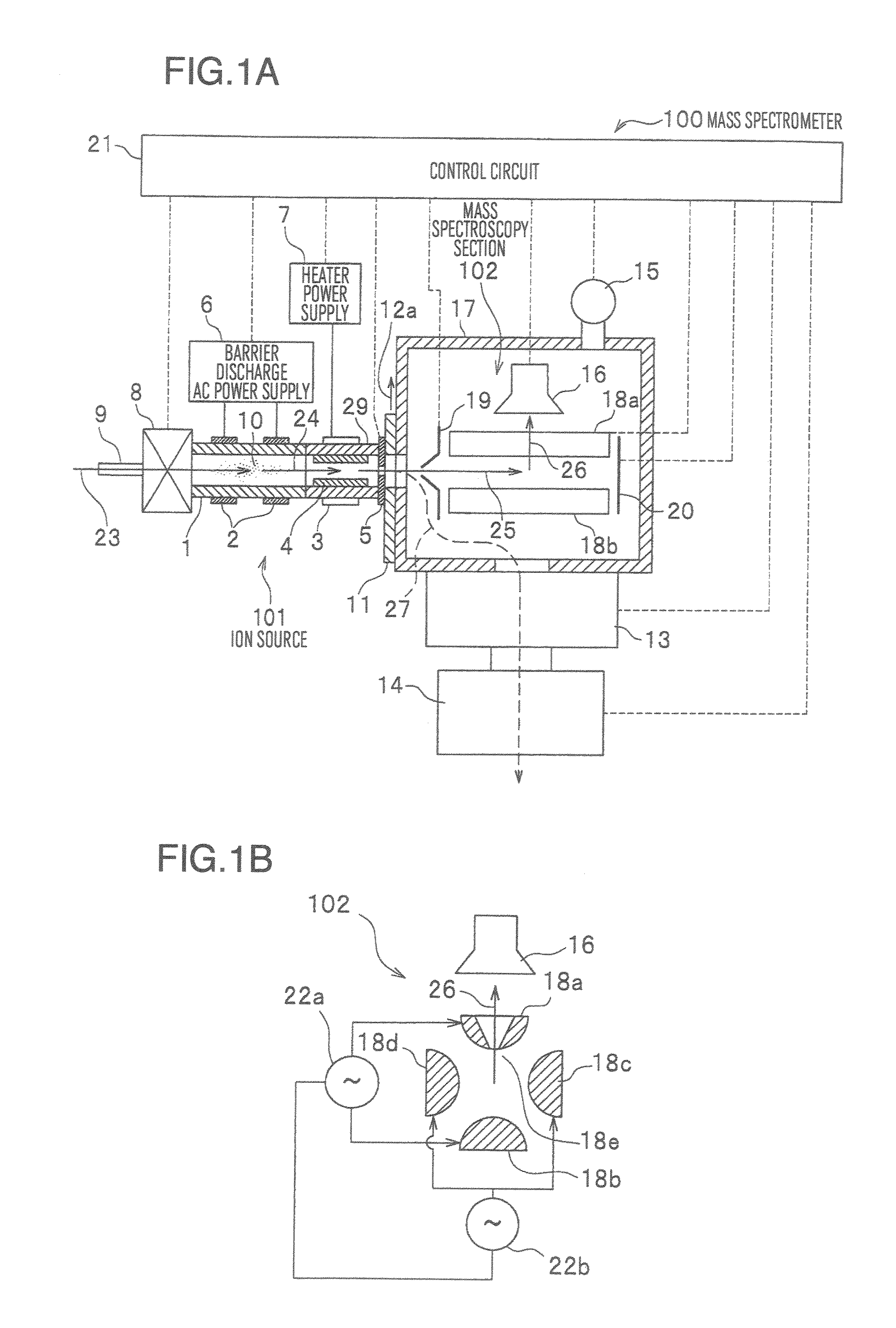
[0062]In FIG. 4, corresponding to a sequence of a method of a mass spectroscopy (frequency sweep scheme) in a mass spectrometer 100 according to a variation of the first embodiment of the present invention, the open / close of the pulse valve in part (a), the pressure in the barrier discharge region in part (b), the pressure in the mass spectroscopy section in part (c), the AC voltage across the barrier discharge electrodes in part (d), the orifice DC voltage in part (e), the in-cap electrode DC voltage in part (f), the end-cap electrode DC voltage in part (g), the trap RF voltage in part (h), the auxiliary AC voltage in part (i), and the on / off of the ion detector in part (j) are shown. The variation of the first embodiment differs from the first embodiment in the mass scan step. In the first embodiment, the voltage values (peak values) of the trap RF voltage and the auxiliary AC voltage are swept as shown in parts (h) and (i) of FIG. 3; in the variation,...
second embodiment
Variation 6 of Second Embodiment
[0082]Illustrated in FIG. 6H is part of a mass spectrometer 100 according to Variation 6 of the second embodiment of the present invention. The mass spectrometer 100 of Variation 6 of the second embodiment differs from the mass spectrometer 100 of Variation 5 of the second embodiment in that a cap 34 embedded and integrated with thin pipes 35 in place of the capillaries 9b and 9c is used to interconnect the pulse valve 8, the vial 31, and the sample ionization container 33. With this configuration, exchange of the vial 31 can be facilitated as compared to the case of interconnection with the help of the capillaries 9b and 9c. Besides, at their ends of the thin pipes 35 of the cap 34 towards the vial 31 a porous filter 36 adapted to pass only gas therethrough is provided to thereby prevent liquid and powder (solid material) from entering the thin pipes 35 of the cap 34.
Third Embodiment
[0083]A configuration diagram of a mass spectrometer 100 according t...
third embodiment
Variation 5 of Third Embodiment
[0090]Illustrated in FIG. 7F is part of a mass spectrometer 100 according to Variation 5 of the third embodiment of the present invention. The mass spectrometer 100 according to Variation 5 of the third embodiment of the present invention has a structure which comprises the upstream side part with respect to the pulse valve 8 of the mass spectrometer 100 of Variation 2 of the third embodiment and the downstream side part with respect to the pulse valve 8 of the mass spectrometer 100 of Variation 3 of the third embodiment combined. Also in Variation 5 of the third embodiment, the vaporized sample 4 passes through the capillary 9c on the downstream side of the pulse valve 8 and is led to the downstream side of the barrier discharge region 10. With this configuration, the barrier discharge region 10 is separated from the flow of sample molecules (gas) 28 and, therefore, the vaporized sample 4 will not be ionized directly in the barrier discharge region 10...
PUM
 Abstract
Description
Claims
Application Information
 - R&D
- Intellectual Property
- Life Sciences
- Materials
- Tech Scout
- Unparalleled Data Quality
- Higher Quality Content
- 60% Fewer Hallucinations
Browse by: Latest US Patents, China's latest patents, Technical Efficacy Thesaurus, Application Domain, Technology Topic, Popular Technical Reports.
© 2025 PatSnap. All rights reserved.Legal|Privacy policy|Modern Slavery Act Transparency Statement|Sitemap|About US| Contact US: help@patsnap.com


