
Optically guided medical tube and control unit assembly and methods of use

a technology of control unit and medical tube, which is applied in the direction of surgery, medical science, gastroscope, etc., can solve the problems of increasing morbidity and mortality, incorrect positioning of feeding tube during the process, and often performing the placement of medical tube, etc., to facilitate the flow of nutrients and medication, facilitate flushing, aspiration, and/or insufflation

Inactive Publication Date: 2012-05-10
THE UNIV OF UTAH
View PDF5 Cites 33 Cited by
  • Summary
  • Abstract
  • Description
  • Claims
  • Application Information

AI Technical Summary

Benefits of technology

[0027]In another aspect of the invention, the optical fibers and wire of the tubing may be coupled to the control unit via a coupling adaptor. The coupling adaptor may also comprise a wheel for receiving the wires of the tubing. The coupling adaptor may be configured to be removably connected to the control unit so as to allow quick and simple engagement of the steering mechanism with the control unit and alignment of the optical fibers with the image capturing device and light source. Alignment of the optical fibers with the image capturing device and light source may be facilitated by including chamfered openings on the control unit at locations where the optical fibers couple to the control unit. Additionally, it may be desirable to construct the coupling adaptor to be lightweight and small enough to go substantially unnoticed when it is intended that a medical tube will be associated with a patient for a prolonged period of time. Thus, for example, the coupling adaptor may remain attached to the medical tube when detached from the control unit.
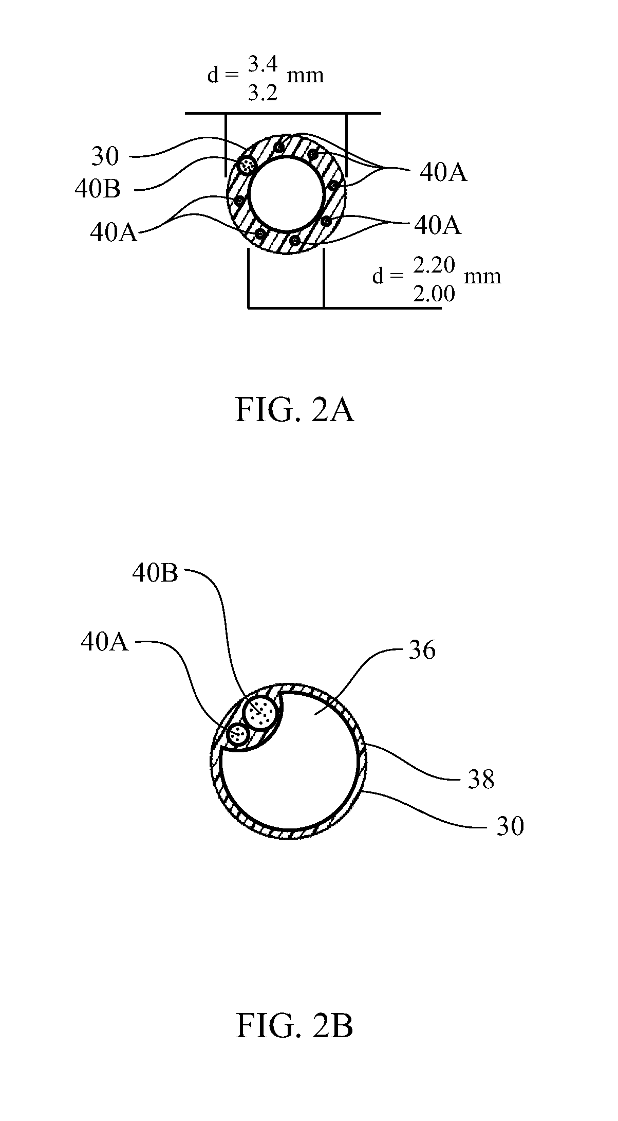
[0037]According to another aspect of the present invention, the optical medical tube may include a tube tip which may provide alignment of imaging. The tip may be connected to the tube so that there is a standoff or gap between the tip and the stylet so as to also facilitate flow of nutrients and medication from a fluid pathway defined by a groove in the stylet and the inner wall of the medical tubing. The gap may also facilitate flushing, aspiration, and / or insufflation by ensuring that sufficient space exists between the tube tip and one or more lumens in the stylet.

Problems solved by technology

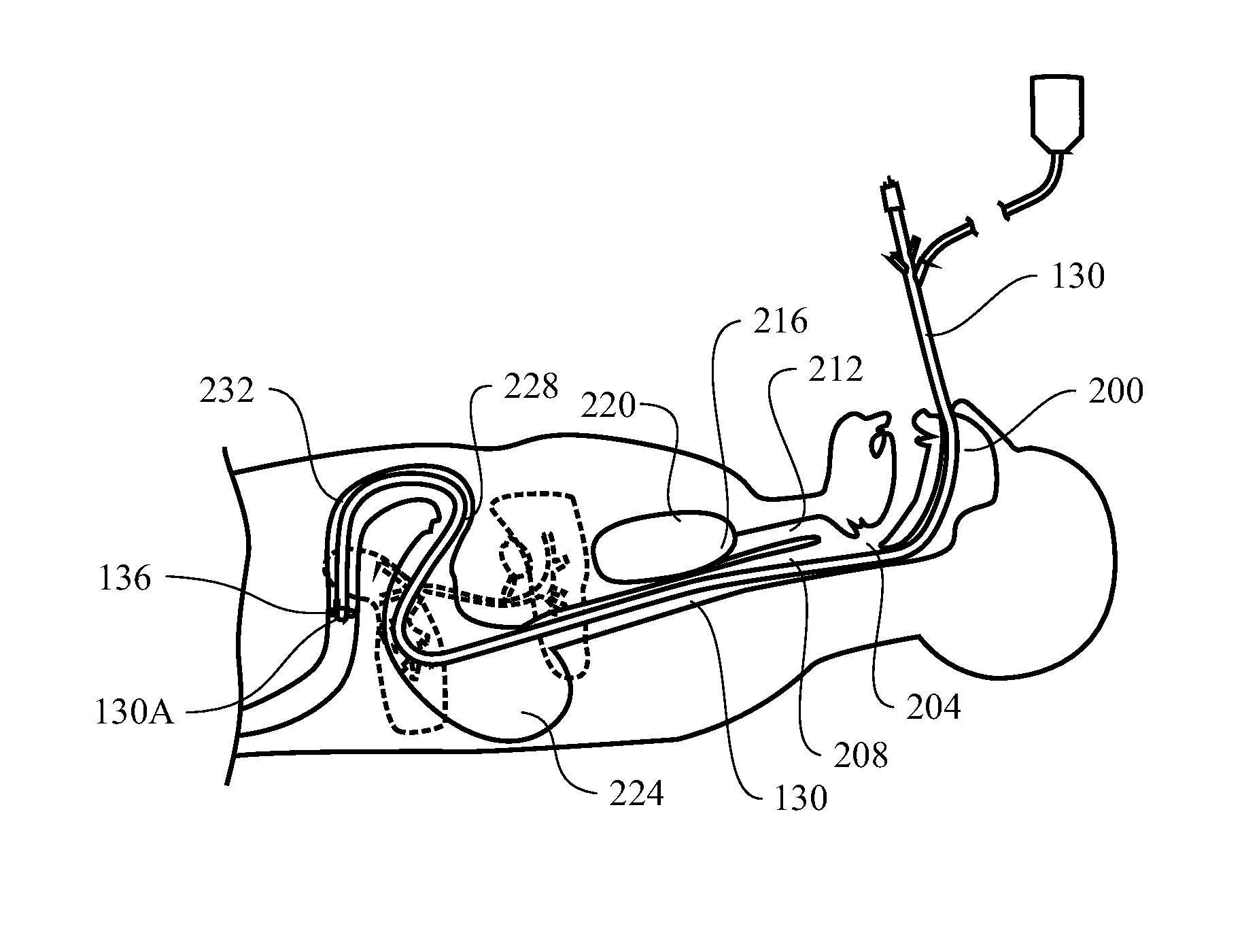
However, placement of most medical tubes is often performed without immediate visual confirmation that the tube has been located at the proper location.
Because the medical personnel cannot see the distal end of the feeding tube during advancement, the feeding tube can be incorrectly positioned during the process.
More commonly, misplacement of the feeding tube results in other serious complications including lung placement or puncture or esophageal puncture.
Additionally, providing any feeding solution through the feeding tube into the lungs likely results in pneumonia with increased morbidity and mortality.
Unfortunately, many common methods for doing so leave patients at substantial risk.
However, these tests only attempt to confirm position after placement when complications may have already occurred.
Moreover, X-ray or fluoroscopic confirmation does not clearly confirm placement in the small bowel rather than the stomach.
Additionally, some of these techniques have additional limitations and drawbacks.
For example, fluoroscopic exams and X-Ray verification can cost $400 or more and can expose the patient and the practitioner to harmful radiation.
If a patient is pregnant, a child or in poor health, exposure to such radiation may be highly undesirable.
Additionally, the use of such verification procedures significantly prolongs the period of time that a patient must wait after a feeding tube is placed before feeding can begin.
If the tube is placed improperly, the wait to begin feeding can take even longer as the process must be repeated.
During this time, the patient is unable to obtain nourishment and any medications which may be delivered via a feeding tube.
Another complication which is common with patients receiving a feeding tube is that the patients are often not coherent.
The patient may be partially sedated or may be delirious.
This requires repetition of the procedure, again subjecting the patients to the risks set forth above.
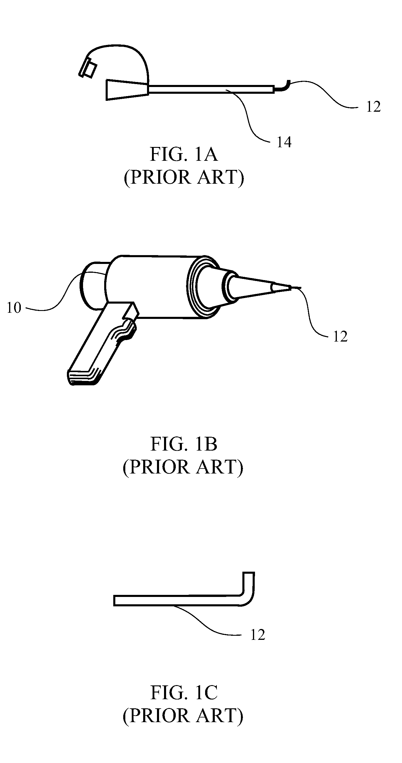
One drawback is that using an endoscope usually takes considerable skill to steer the tip of the endoscope through complex and tortuous paths in the body, which can be made more difficult if the tip cannot be steered in multiple directions.
Furthermore, endoscopy procedures are typically performed by physicians, often requiring a longer wait time before a properly trained physician is available to place the feeding tube, as opposed to the wait time if medical personnel other than a physician could place the tube.
Another drawback of using an endoscope to place a feeding tube is that, because the endoscope is typically placed through the mouth, an additional procedure must be used if the feeding tube is to be used nasoenterically.
Also, the procedure usually requires conscious sedation which increases the risk and cost of the procedure.
Additionally, an endoscope is a complex, expensive medical device.
One significant cost associated with the manufacture of an endoscope can be the optical fibers used to transmit light and images.
Optical fiber with a small enough diameter, however, is typically more expensive.
The larger optical diameter of the cheaper, plastic optical fiber, however, may limit the amount of space for additional lumens that may be used to perform additional functions.
Furthermore, because an endoscope is a complex and expensive medical device it is generally not discarded after use in one patient, but rather it is reused in subsequent patients.
The procedure of cleaning and disinfecting an endoscope is both time consuming and expensive and may involve mechanical cleaning, leakage testing, disinfecting the endoscope chemically for an appropriate amount of time, and then rinsing and drying the endoscope.
Each of the above-referenced methods for placing a feeding tube also has problems with subsequently confirming that the feeding tube remains properly placed.
Although the current discussion has been directed at the disadvantages of current methods for placing a feeding tube, similar disadvantages exist with current procedures for placing other medical tubes.
Of course, it is often difficult to tell if the situation has been fully alleviated, if the device has become misplaced, or if the symptoms have simply been reduced.

Method used


Image

  • Optically guided medical tube and control unit assembly and methods of use
  • Optically guided medical tube and control unit assembly and methods of use
  • Optically guided medical tube and control unit assembly and methods of use

Examples


Embodiment Construction

[0084]Before the present invention is disclosed and described, it is to be understood that this invention is not limited to the particular structures, process steps, or materials disclosed herein, but is extended to equivalents thereof as would be recognized by those ordinarily skilled in the relevant arts and by the terms set forth in the claims. It should also be understood that terminology employed herein is used for the purpose of describing particular aspects of the invention only and is not intended to limit the invention to the aspects or embodiments shown.

[0085]It must be noted that, as used in this specification and the appended claims, the singular forms “a,”“an,” and “the” may include plural referents unless the context clearly dictates otherwise. Thus, for example, reference to “an optical fiber” may include one or more of such optical fibers, and reference to “the lens” may include reference to one or more of such lenses.

[0086]As used herein, “subject” or “patient” refe...


PUM


Abstract

An optical medical tube and control unit assembly and methods of using the same are provided. The optical medical tube may include a steering mechanism and an imaging device which provides the user a visual aid when placing a tube in the body of a patient. The optical medical tube may be coupled to a coupling adaptor to enable quick and easy connecting of the imaging device and steering mechanism of the tube with a control unit such that a single control unit may be used to place multiple feeding tubes or confirm that a feeding tube remains in its proper position without the need for lengthy sterilization procedures between uses.

Description

RELATED APPLICATIONS[0001]The present application is a continuation-in-part of U.S. patent application Ser. No. 12 / 756,129, filed Apr. 7, 2010, which is expressly incorporated herein by reference and which claims the benefit of U.S. Provisional Patent Application No. 61 / 168,144, filed Apr. 9, 2009, which is expressly incorporated herein by reference, and also claims the benefit of U.S. Provisional Patent Application No. 61 / 425,730, filed Dec. 21, 2010, which is expressly incorporated herein by reference.THE FIELD OF THE INVENTION[0002]The present invention relates to devices and methods used to view an area when direct line-of-sight observation is not feasible. In some aspects, the invention relates to an optically guided medical tube and control unit assembly that may be used for prolonged and / or repeated viewing of an area that would otherwise be difficult or impossible to view with the naked eye, such as the interior anatomy of a human or animal. In other aspects, the invention r...

Claims


Application Information

Patent Timeline
Patent Type & Authority Applications(United States)
IPC IPC(8): A61B1/06A61B1/00
CPCA61B1/00052A61B1/07A61B1/2733A61B1/2736A61J15/0007A61B1/0607A61J15/0046A61J15/0073A61M25/0147A61J15/0049A61J15/0069A61J15/0015
Inventor NIEMAN, TIMOTHY R.PERRY, TRENT J.
Owner THE UNIV OF UTAH
Learn More