
Two-beam optical coherence tomography apparatus

a tomography and optical coherence technology, applied in the field of two-beam optical coherence tomography apparatus, can solve the problems of longer scanning time or longer time needed to obtain a tomography image, and achieve the effects of improving the measurement sensitivity of doppler frequency shift, high sensitivity, and increasing scanning speed

Active Publication Date: 2012-05-17
UNIV OF TSUKUBA
View PDF7 Cites 88 Cited by
  • Summary
  • Abstract
  • Description
  • Claims
  • Application Information

AI Technical Summary

Benefits of technology

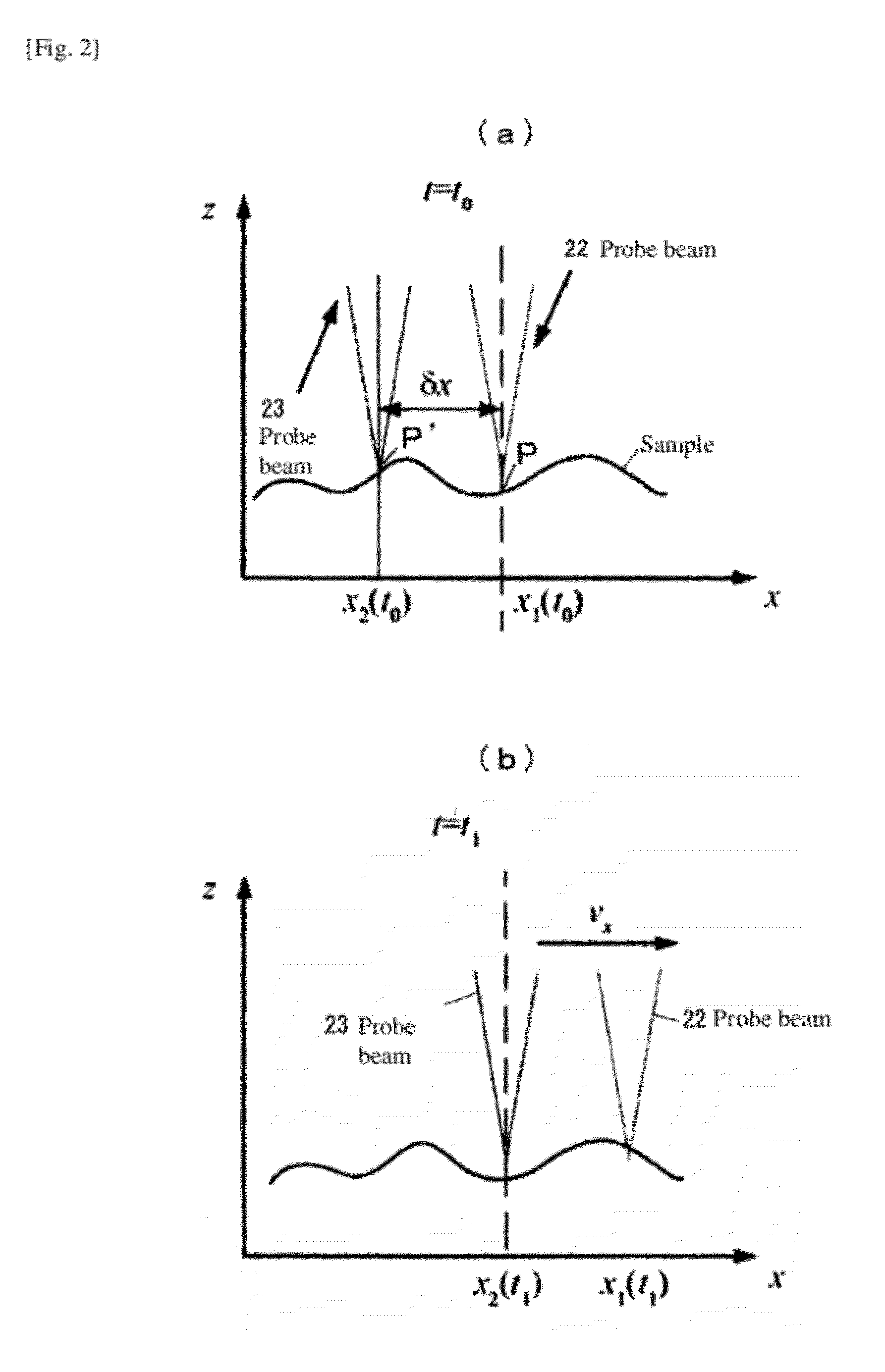
[0039]With a two-beam optical coherence tomography apparatus pertaining to the present invention, the same location of the sample can be measured at different times using two polarized beams shifted by a specified interval in the scanning direction, even when the scanning speed is increased, to obtain two tomography images reflecting different measurement timings, and these two tomography images can be used to obtain the amount of change in phase or frequency shift (change in frequency) between different times at the same location of the sample, thereby allowing for high-speed tomography image measurement of flow rate distribution at high sensitivity.
[0040]Also with normal Doppler OCT that measures the same location of the sample using one probe beam, an attempt to measure the same location of the sample twice with a minimum time difference using one probe beam with the aim of increasing the scanning speed would generate noise because the time difference is too short and consequently the Doppler frequency shift cannot be measured sufficiently. Under the present invention, on the other hand, data of two tomography images is used to calculate the amount of change in phase or frequency shift, and by increasing the time difference at which these two tomography images are obtained, the measurement sensitivity of Doppler frequency shift can be improved.

Problems solved by technology

Accordingly, measurement requires two irradiations of a probe beam onto the applicable location of the sample at an interval of at least Δt, which presents the problem of longer scanning time or longer time needed to obtain a tomography image.
In effect, Doppler OCT has the problem of having to lower the scanning speed and take time to measure the same location multiple times in order to raise the sensitivity of the flow rate.

Method used


Image

  • Two-beam optical coherence tomography apparatus
  • Two-beam optical coherence tomography apparatus
  • Two-beam optical coherence tomography apparatus

Examples


examples

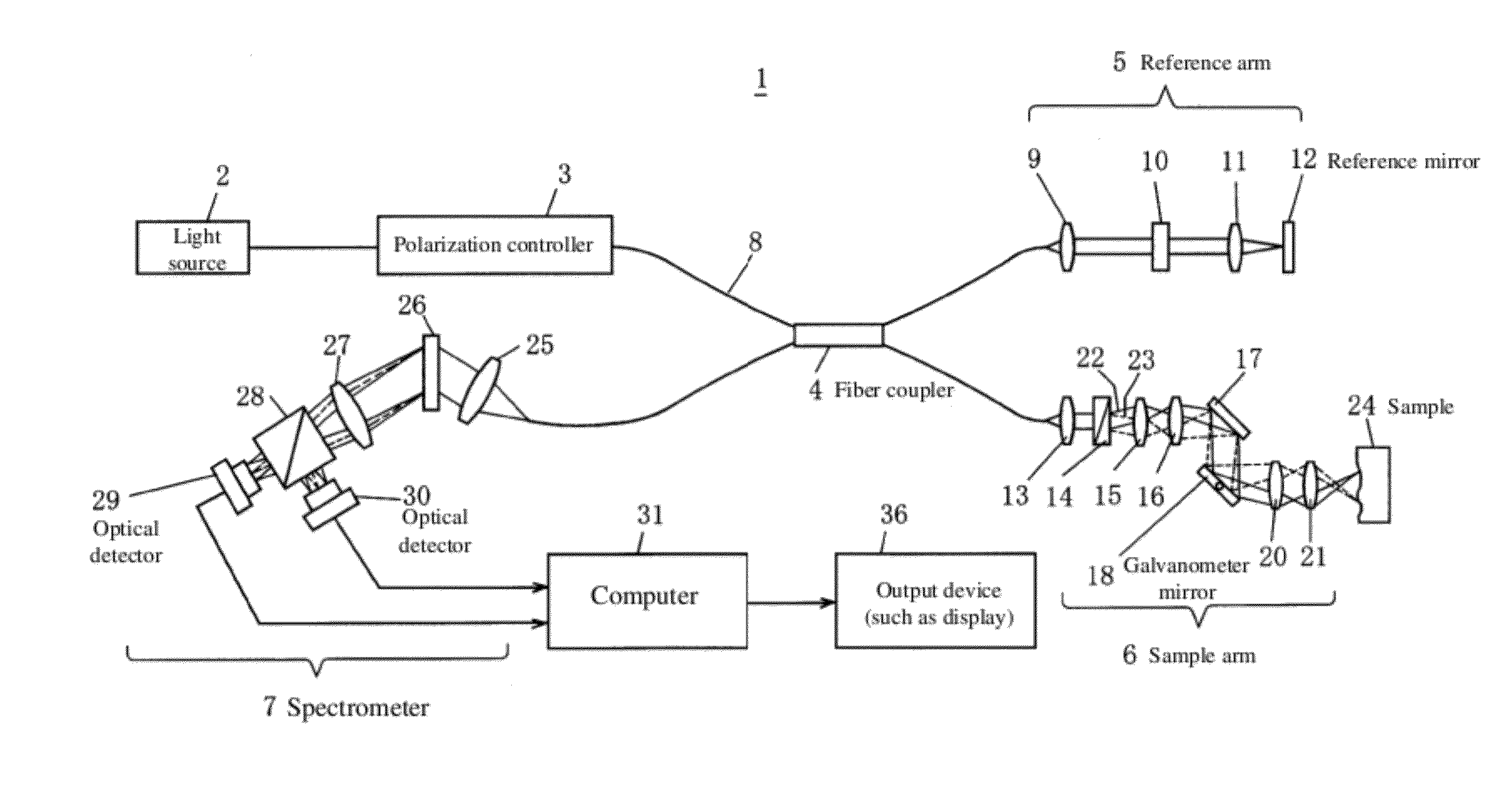
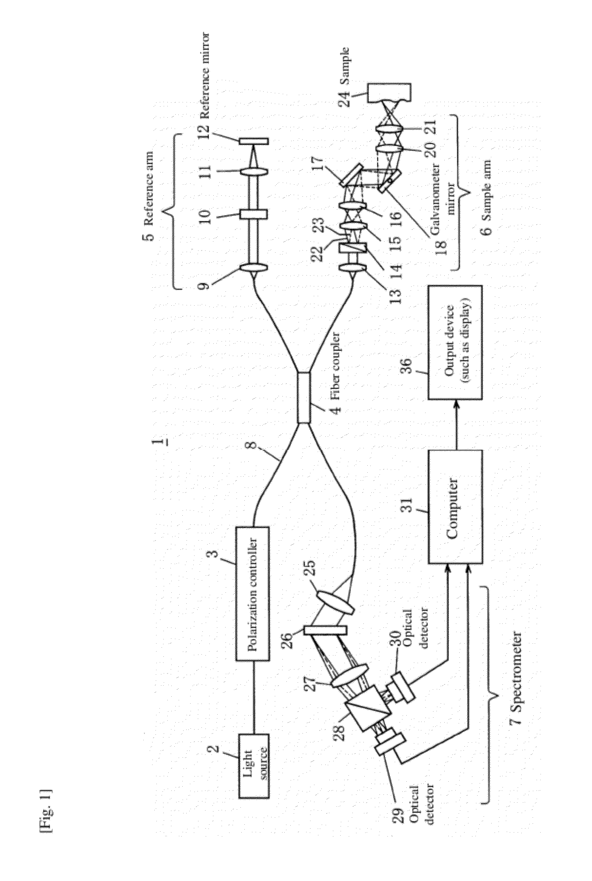
[0078]A measurement experiment was conducted using the two-beam optical coherence tomography apparatus shown in FIG. 1, where the sample 24 was a human retina. Using a super-luminescent diode (SLD) as the wideband light source, the polarization direction of wideband light from the light source was controlled by the polarization controller 3 to implement conversion in such a way that the horizontal component and the vertical component of linear polarization became 1:1, and the converted light was introduced to the fiber coupler 4 via the optical fibers 8. Then, the linearly polarized light was caused to enter the reference arm 5 and sample arm 6 from the fiber coupler 4.

[0079]The backscattering light from the sample arm 6 and reference light from the reference arm 5 were merged by the fiber coupler 4 to cause interference, which was followed by spectroscopy at the diffraction grating 26 and the resulting light was then separated into the horizontally polarized component and the verti...


PUM


Abstract

The scanning speed of a sample in Doppler OCT, etc., is increased to enable quick measurement of blood flow rate, blood flow volume, etc. Wideband light from a light source 2 is linearly polarized by a polarization controller 3 and this linearly polarized beam is split into vertically polarized light and horizontally polarized light using a Wollaston prism 14 at a sample arm, which are then irradiated simultaneously onto two different locations of the sample in the scanning direction using a galvanometer mirror18, and reference light from a reference arm 5 and object light from a sample arm 6 are merged and caused to interfere with each other, with the resulting interference signal light passed through a diffraction grating 26 for spectroscopy, while the horizontal component and vertical component are separated by a polarized beam splitter 28, to simultaneously measure the components with two polarization-sensitive optical detectors 29, 30 and thereby obtain two tomography images of the same location at different times by one mechanical scan, thus allowing the amount of temporal change in phase to be measured using the two tomography images.

Description

TECHNICAL FIELD[0001]The present invention relates to a two-beam optical coherence tomography apparatus, and specifically to a two-beam optical coherence tomography apparatus that can be applied for quantitative measurement apparatuses for eye fundus blood flow volume (blood flow volume in the blood vessels of the retina).BACKGROUND ART[0002]Traditionally “optical coherence tomography” (OCT) has been used to understand information of the inside of an object, or specifically the differential structure of refractive index distribution, in a nondestructive manner at high resolution.[0003]OCT is a nondestructive tomography measurement technology used in the medical field, etc. (refer to Patent Literature 1). OCT uses light as probe beam (measurement light), which provides the advantage of being able to measure refractive index distribution, spectral information and polarization information (birefringence distribution) of a measuring target, among others.[0004]A basic OCT 53 is based on ...

Claims


Application Information

Patent Timeline
Patent Type & Authority Applications(United States)
IPC IPC(8): G01B9/02
CPCA61B3/102G01N21/4795A61B5/0066A61B3/1233
Inventor YASUNO, YOSHIAKIMAKITA, SHUICHIITO, MASAHIDE
Owner UNIV OF TSUKUBA
Learn More