Ultra-pumps systems

a technology of ultra-pumps and pumps, which is applied in the direction of functional valve types, separation processes, and well accessories, etc., can solve the problems of large quantities of petroleum origin liquids involved, difficult to recover, and loss of groundwater, so as to reduce water production, maximize oil recovery, and effective use

Inactive Publication Date: 2012-05-24
DYER RICHARD J
View PDF13 Cites 11 Cited by
  • Summary
  • Abstract
  • Description
  • Claims
  • Application Information

AI Technical Summary

Benefits of technology

[0034]The lower end of the chamber is provided with a non-return inlet valve which is preferably a flap valve having a flap hinged about a vertical axis member to open and close on the openings or holes in the lower end cover of the chamber. However, other suitable inlet valves can be used from an assortment of materials. The inlet / flap valve communicates with the exterior of the chamber allowing fluid to pass through the openings / holes in the end cover / cap into the chamber but preventing fluid from passing through the flap valve from the chamber in the reverse direction.
[0035]One of the main advantages of the present invention pump apparatus is the very effective use in shallow wells (such as a depth from 40 feet to 1000 feet). These type wells are not on primary production locations, but are deemed as low producers, for example, producing a few gallons of fluid (like oil) per day to 4 or 5 barrels of fluid (like oil) per day. In the initial operation, it is the object to establish the static fluid level of the well. The pump apparatus is then lowered down the bore into the oil and water areas. The well is pumped down to a point until water is recovered, then measured for gallon amounts. The well is shut-in for 24 hours and then the static fluid level is taken again and compared with the day before. Again, the well is pumped down to the water level and shut down. The process is repeated until it is determined how much oil the well will produce daily without significant water content and the fluid level returns to the static level. A solenoid valve controller, for gas injection is then set to allow pumping to begin and extend for a period of time during which only the desired fluid / oil pad is removed from the well. The gas exhaust time can range from a few minutes to an hour with the pressure cycle ranging from a few seconds to 30 seconds, or more. The pressure is set at the well head controller with the use of an adjustable pressure regulator. Regulating the gas pressure at each well is important because the pump apparatus in each well is set at different levels and a different diameter size pump apparatus is used depending upon the different gravities of the desired fluid. One significant feature of the present invention relates to the fact that only one gas compressor can be used to operate numerous wells such as from 4 wells to 50 wells. One compressor (as shown in FIG. 5) can be utilized to provide a trunk line to each of these wells at a set pressure (in general, pressures are higher then what is needed to effectively make use of the pump apparatus) so at the controller, a regulator is attached to adjust and regulate the desired pressure to each pump apparatus. Then the timer is set for the pumping cycles for each of the individual wells. In the event air or gas get into the production line going to the tank facility, it can be viewed at the wash tank from the vent at the top of the tank or a gas vent can be installed in the production line to reduce air or gas to the facilities (fisher gas vent). Furthermore, the individual wells can be regulated for pressure, cycles on exhaust, and pressure so that air / gas does not exit the pump apparatus.
[0036]As previously mentioned, the significance and importance of this unique air / gas pumping system in this industry is to reduce water production and maximize oil recovery, with significantly reduced capital investment. This is accomplished, as described herein, by only skimming the fluid / oil pad off each well produced. This significantly reduces disposal problems with produced water and permits the continued oil production during adverse weather conditions, such as during winter months, with the greatly reduced production of undesirable water and the inherent disposal problems associated therewith.

Problems solved by technology

It is well known that at refineries and other facilities where petroleum products are processed and handled, substantial quantities of the petroleum origin liquids involved (hereinafter sometimes referred to for convenience of reference and description as petroleum origin hydrocarbons or “hydrocarbons”), are lost into the ground due to spillage and the like.
These prior art approaches have involved a number of problems that in the past have made it difficult to recover these hydrocarbons, in quantities adequate in quantity and quality to warrant commercial exploitation of same, and consequently limited incentives to try to recover small quantities of the hydrocarbons.
For example, “rocker arms” rotating devices are highly expensive and thus are not economically feasible to install in such locations wherein small quantities of oil are located; the present invention, however, provides an apparatus, ultra pumping system, or device which costs about 3-5 percent of the cost of a rocker arm apparatus.
Further, mechanical pumps that are employed are ordinarily electrically driven, and since hydrocarbons are highly inflammable, fire danger is an ever present problem.
Also, as the hydrocarbons involved are removed, the pumping speeds have to be changed to be commensurate with the hydrocarbons remaining to be recovered, which requires expensive variable speed drives for the pump equipment involved.
Thus, where centrifugal and other mechanical types of water pump equipment are involved for draw down purposes, some type of level sensing device and expensive variable speed controls would be required in order for the equipment to operate properly, and as draw down pumps are usually suspended near the bottom of the well, a substantial amount of debris will be passing through the pump with resulting high pump maintenance requirements.
In view of environmental concerns regarding the production of large quantities of undesirable water and the disposal thereof, the above practices greatly inhibit the recovery of hydrocarbons / oil from underground locations, including but not limited to, wells that have been shut-in or are no longer in operation.
Pumping apparatus for the recovery of liquid hydrocarbons / oil (fluids) have been used for many years, but as the quantities of desired liquids has decreased, the use of complex and / or expensive equipment, such as rocker arms, cannot justify the continued use thereof.
A problem with the existing designs is that they often require numerous component parts, including moving parts, and therefore tend to be complex, capital intensive and expensive to operate.
Stationary inlets may be mispositioned out of the product when the water level drops, or they can be completely submerged under the water if the level rises to an unacceptably high degree.
Hydrophobic screens can be easily fouled and plugged, and floating inlets can hang up for various reasons.
In viewing the figures / drawings of each of the prior art patents cited above, it can readily be seen that each one involves complex equipment arrangements, numerous moving parts (subject to be worn out and / or not properly functioning) and the costs thereof are prohibitive in light of the quantities of fluids / oil to be recovered.

Method used


Image

  • Ultra-pumps systems
  • Ultra-pumps systems
  • Ultra-pumps systems

Examples


examples 1-29

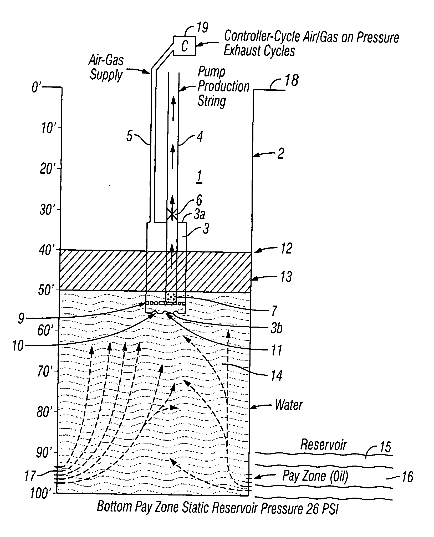
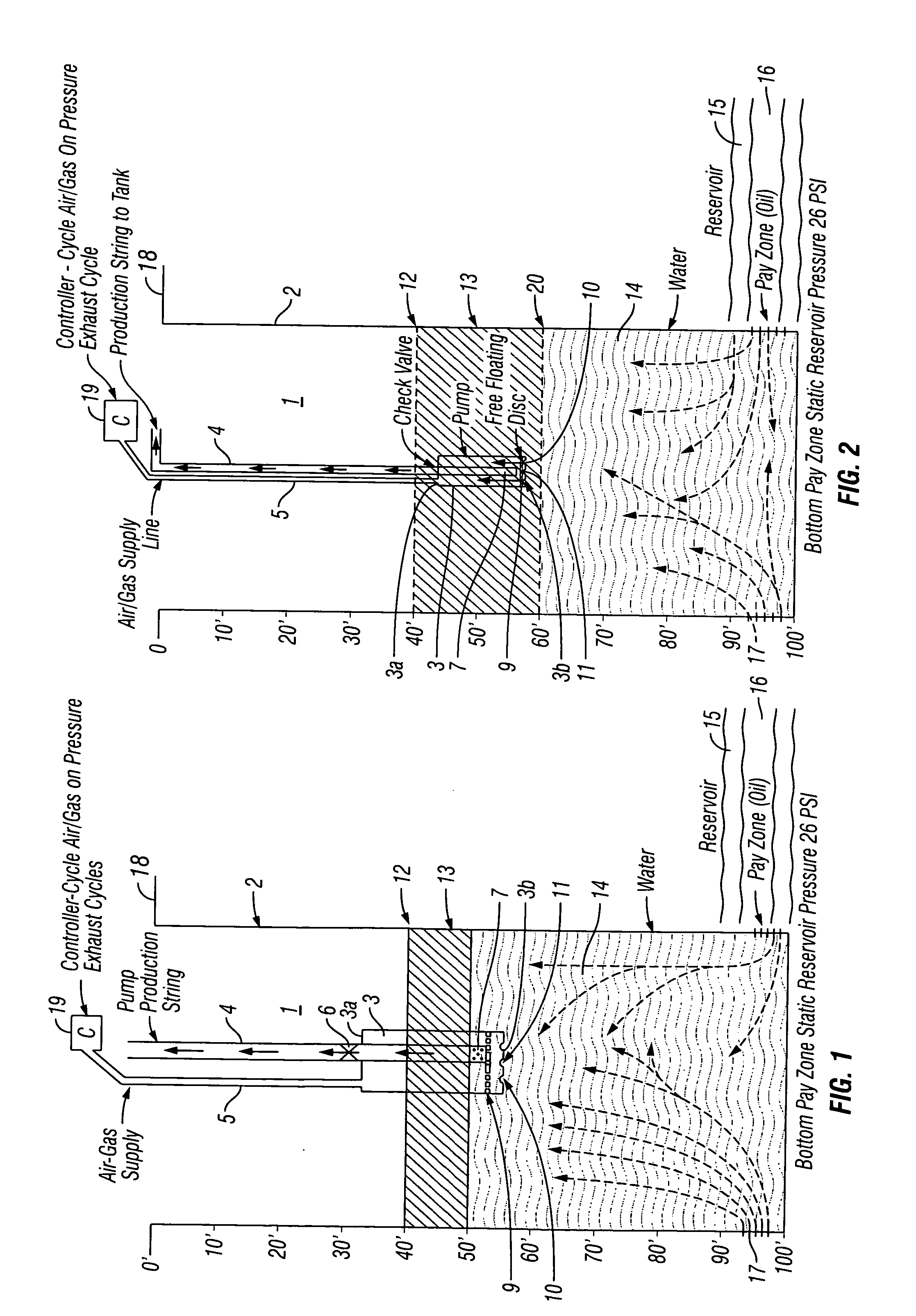
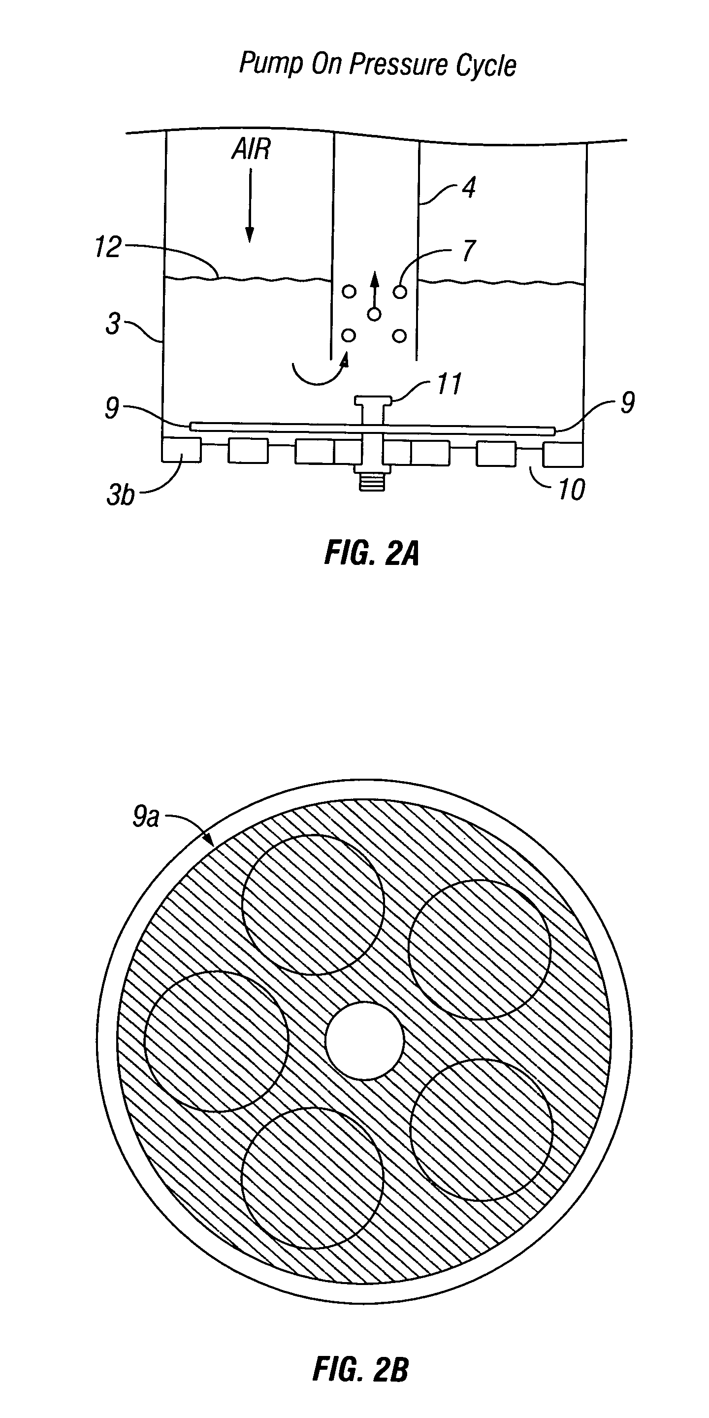
[0076]While FIGS. 1 through 5 are drawings / schematics showing the ultra pumping system, the ultra pumping system per se was tested in an oil field in Crook County, Wyo., and are submitted as Examples 1-29. In general, these figures have been briefly described above in conjunction with the general description of the drawings. The diameter size of the pump chamber and the length thereof was predetermined in order to test different sizes and lengths in wells of different depths. The pump chamber diameter size, length and the well depth are shown in Table 1. The air pipe and production string / pipes at the top of the pump chamber were, respectively, connected to flexible poly tubing, and then these were positioned just outside the top cover of the pump chamber. The overall chamber (with the connected poly tubing), was then the lowered into the well and well within the static fluid level (Table 1) which had been measured earlier based upon a “plum-bob” measurement. The initial operation o...


PUM

PropertyMeasurementUnit
lengthaaaaaaaaaa
diameteraaaaaaaaaa
pressureaaaaaaaaaa

Abstract

This invention provides a positive displacement gas operated pump and pumping system for pumping fluids such as hydrocarbons / oil as well as solids that may be suspended in such fluids. More specifically, the invention relates to a method and apparatus for the recovery of hydrocarbons / oil from underground water tables and / or where water flooding has previously been used to further extract hydrocarbons / oil from underground areas, but economics prevent further recovery from such areas and / or wells.

Description

RELATED PATENT APPLICATIONS[0001]This present pending utility patent application is derived from pending provisional patent application Ser. No. 61 / 458,200 filed on Nov. 20, 2010 and is the priority date for this pending utility patent application.FIELD OF THE INVENTION[0002]This invention relates to an ultra pump system for reducing costs and increasing production in pumping fluids, particularly from underground locations, and for the provision of a environmentally friendly operation thereof. For example, this invention provides a positive displacement gas operated pump and pumping system for pumping fluids such as hydrocarbons / oil as well as solids that may be suspended in such fluids. More specifically, the invention relates to a method and apparatus for the recovery of hydrocarbons / oil from underground water tables and / or where water flooding has previously been used to further extract hydrocarbons / oil from underground areas, but economics prevent further recovery from such area...

Claims


Application Information

Patent Timeline
Patent Type & Authority Applications(United States)
IPC IPC(8): E21B43/00F16K21/04
CPCE21B43/129Y10T137/86019E21B43/13
Inventor DYER, RICHARD J.
Owner DYER RICHARD J
Why Eureka
Try Eureka