Fluorescent analysis method

a fluorescent analysis and fluorescence technology, applied in the field of fluorescence analysis apparatus, can solve the problems of unnecessary purification and amplification, expensive cameras become necessary, etc., and achieve the effects of improving detection efficiency, high throughput, and reducing the number of errors

Inactive Publication Date: 2012-05-24
HITACHI HIGH-TECH CORP
View PDF0 Cites 63 Cited by
  • Summary
  • Abstract
  • Description
  • Claims
  • Application Information

AI Technical Summary

Benefits of technology

[0020]With this invention, without impairing the measurement accuracy, the required number of pixels of a two-dimensional sensor with respect to regions to which the to-be-measured oligonucleotides should be immobilized can be reduced from hundreds of times of a traditional number to ten times or less, thereby increasing the detection efficiency. Consequently, in the case of using the same two-dimensional sensor, it is possible to obtain fluorescence images from an increased number of regions at a time, thus enabling achievement of high throughput. In addition, in the case of using a camera with a less number of pixels, it becomes possible to perform the measurement at lower costs.
[0021]Also, with this invention, in a case where the number of those regions with the to-be-measured oligonucleotides being immobilized thereto is the same, it becomes possible to efficiently detect with a smaller number of pixels, thereby making it possible to lower the price of the two-dimensional sensor. Further, since it is possible to equalize the optical resolution to a degree of the layout interval of the oligonucleotide-immobilized regions, it is no longer required to use a condenser lens with a large numerical aperture so that a low-price lens can be used and a liquid-immersion lens is not needed to be used, thus enabling improvement of operability.

Problems solved by technology

Also, since in this scheme there is a potential to enable determination of the base sequence with respect to each single DNA molecule, there is a possibility of rendering unnecessary the purification and amplification of sample DNA in cloning, PCR, or the like which have been problematic in the prior art so that speedup of genome analysis and genetic diagnosis is expected.
Incidentally, in this method, sample DNA fragment molecules to be analyzed are randomly immobilized to the substrate surface so that an expensive camera becomes necessary having a number of pixels that is several hundred times greater than the number of captured DNA fragment molecules.

Method used


Image

  • Fluorescent analysis method
  • Fluorescent analysis method
  • Fluorescent analysis method

Examples


embodiments

[0064]While this invention is set forth below based on embodiments, the invention is not limited thereto.

first embodiment

[0065]An explanation is given of an apparatus and a method for capturing DNA fragments of a to-be-analyzed sample onto a substrate surface one molecule at a time at equal intervals, elongating in an almost one-by-one manner at a time, and for detecting incorporated fluorescent labels on a per-molecule basis, thereby determining a base sequence. More specifically, while letting one cycle consist of a process of performing DNA polymerase reaction using four kinds of dNTP derivatives, which are incorporated into a template DNA as substrates of DNA polymerase and able to stop DNA strand elongation reaction due to the presence of a protecting group and which also have detectable labels, a sequential process of detecting such incorporated dNTP derivatives by fluorescence or the like, and a process of restoring the dNTP derivatives to an state able to elongate, the cycle of these processes is repeated to thereby determine the base sequence of the sample DNA. Incidentally, since this operat...

second embodiment

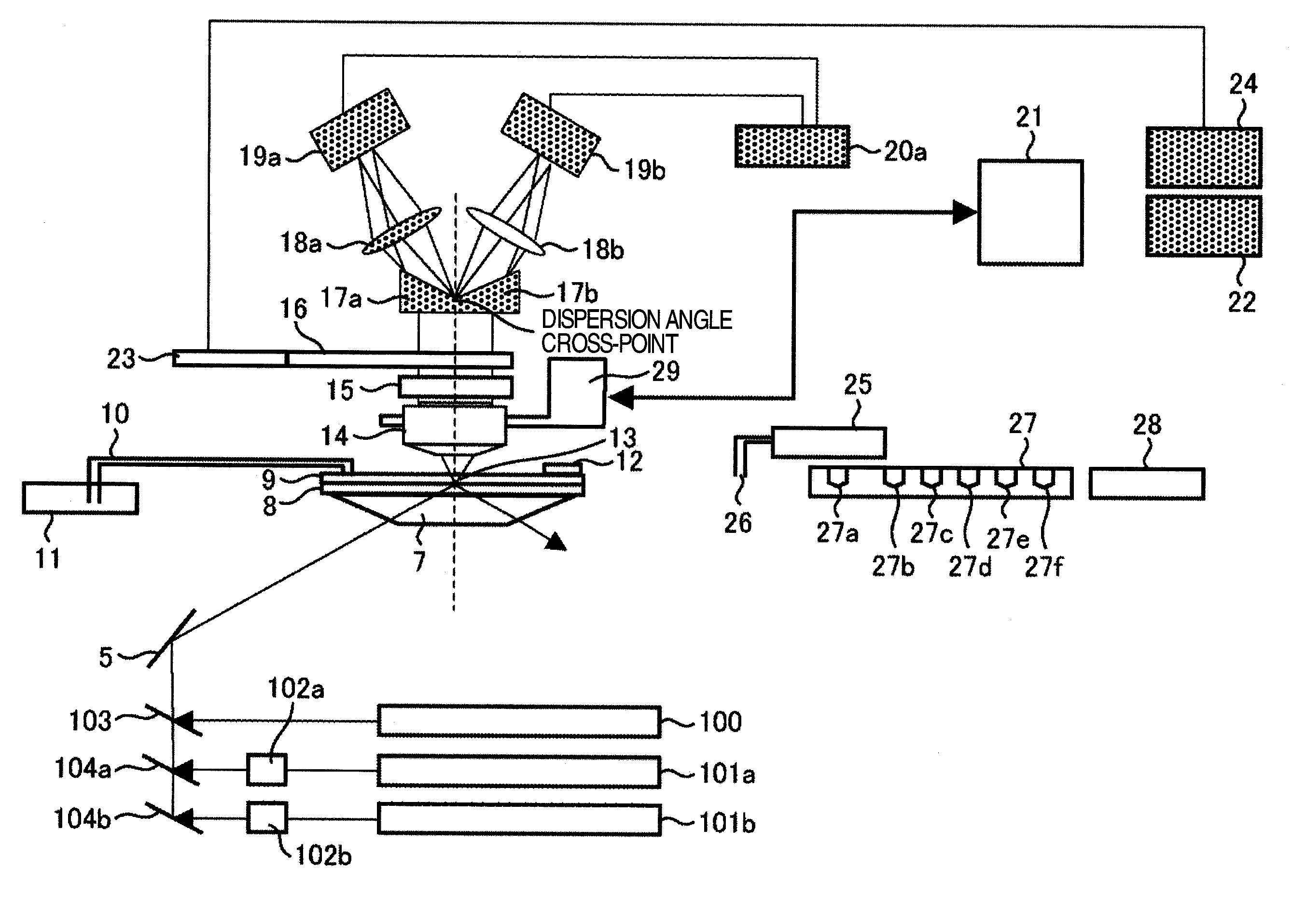
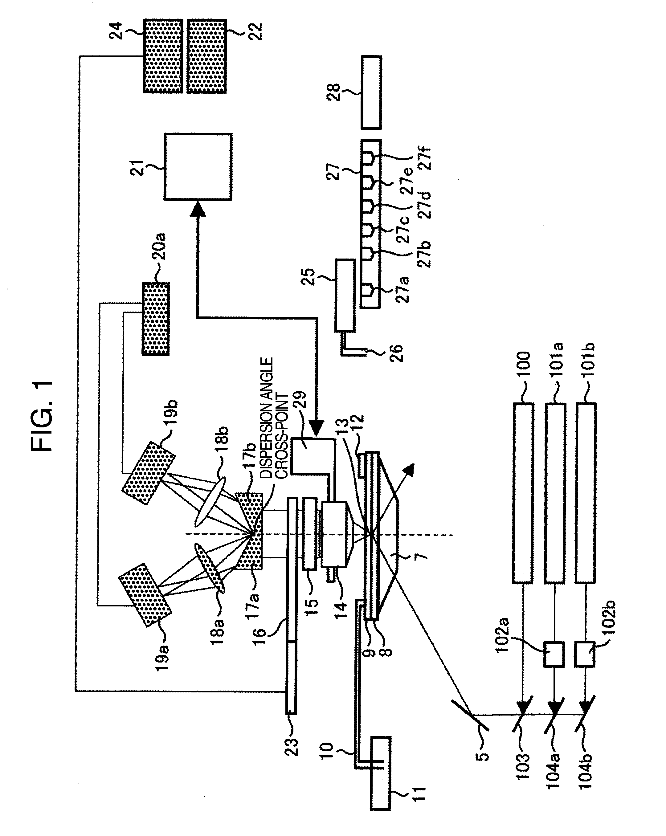
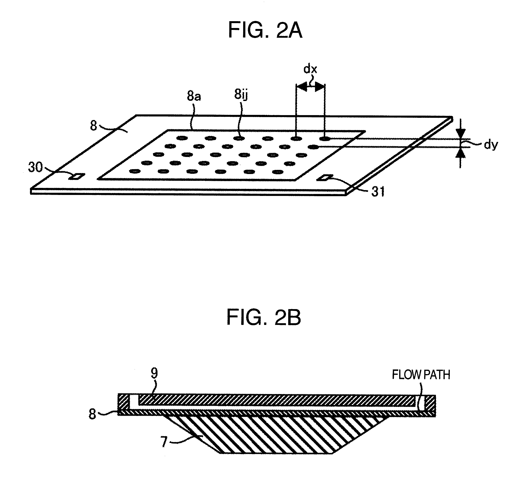
[0104]FIG. 4 is a configuration diagram of a DNA test apparatus using the fluorescence analysis method of this invention. While FIG. 1 is the microscope using prism total-internal-reflection scheme, FIG. 4 is a microscope with the laser incident direction and the fluorescence detection direction being the same direction. As this type of apparatus, there is also a microscope of objective-lens total-internal-reflection scheme capable of performing single-molecule detection by irradiating a laser from the peripheral part of an objective lens at an angle ensuring the occurrence of total internal reflection, which is also employable in embodiments below. The apparatus has a configuration similar to that of a microscope and is arranged to measure by fluorescence detection the elongated states of DNA molecules to be captured onto a substrate 8. The substrate 8 has a structure shown in FIG. 2. The substrate 8 is at least partly made of a transparent material and material such as synthetic q...


PUM

PropertyMeasurementUnit
diameteraaaaaaaaaa
diameteraaaaaaaaaa
sizeaaaaaaaaaa

Abstract

Disclosed is a fluorescent analysis method whereby the throughput in DNA sequence analysis or the like can be improved. The method comprises irradiating a substrate, which carries biological molecules such as oligonucleotides immobilized thereon, with light for fluorescent measuring, collecting the generated fluorescence, dispersing the collected light, forming an image by focusing the light on a two-dimensional sensor, and then detecting the fluorescence with the two-dimensional sensor. In this method, since wavelengths are dispersed in different directions and then detected at the same time, the intensity of each dispersed wavelength and the position of the subject of spectroscopic imaging can be calculated even in the case where the wavelength dispersion distance is longer than the inter-lattice distance.

Description

TECHNICAL FIELD[0001]The present invention relates to a photometric analysis apparatus and also relates to an optical measurement / analysis apparatus for performing photometric analysis by irradiating light onto bio-related material, such as, for example, DNA, RNA, or protein.BACKGROUND ART[0002]Traditionally, methods for projecting excitation light onto an object disposed on the surface of a substrate to thereby observe the shape of such object have been proposed. For example, Patent Literature 1 discloses therein an apparatus which irradiates a transparent substrate with excitation light as output from an excitation light source and then forces the excitation light to perform total internal reflection within it, thereby producing an evanescent wave on the substrate surface, thus detecting scattered light of the evanescent wave arising from a sample on the substrate. It should, however, be noted that the apparatus disclosed in Patent Literature 1 is not arranged to disperse the scat...

Claims


Application Information

Patent Timeline
Patent Type & Authority Applications(United States)
IPC IPC(8): G01J3/443G01N21/64
CPCG01N21/6452G01N21/6458G01N21/648G01N33/54393G01N2021/6419G01N2021/6421G01N2021/6441G01N33/54366
Inventor MATSUI, TAKUYAINABA, RYOJI
Owner HITACHI HIGH-TECH CORP
Why Eureka
Try Eureka