

Apparatus and method for operating optical microcavity by light emitting diode
a technology of light-emitting diodes and optical microcavities, which is applied in the direction of optical radiation measurement, fluorescence/phosphorescence, luminescent dosimeters, etc., can solve the problems of insufficient excitation of fluorescent labels, inability to believe that such low power excitation can be successfully applied to wgm excitation,
- Summary
- Abstract
- Description
- Claims
- Application Information
AI Technical Summary
Benefits of technology
Problems solved by technology
Method used
Image

Examples
working examples
(iv) WORKING EXAMPLES
Example 1
Amplification of Cavity Modes Via Stimulated Emission
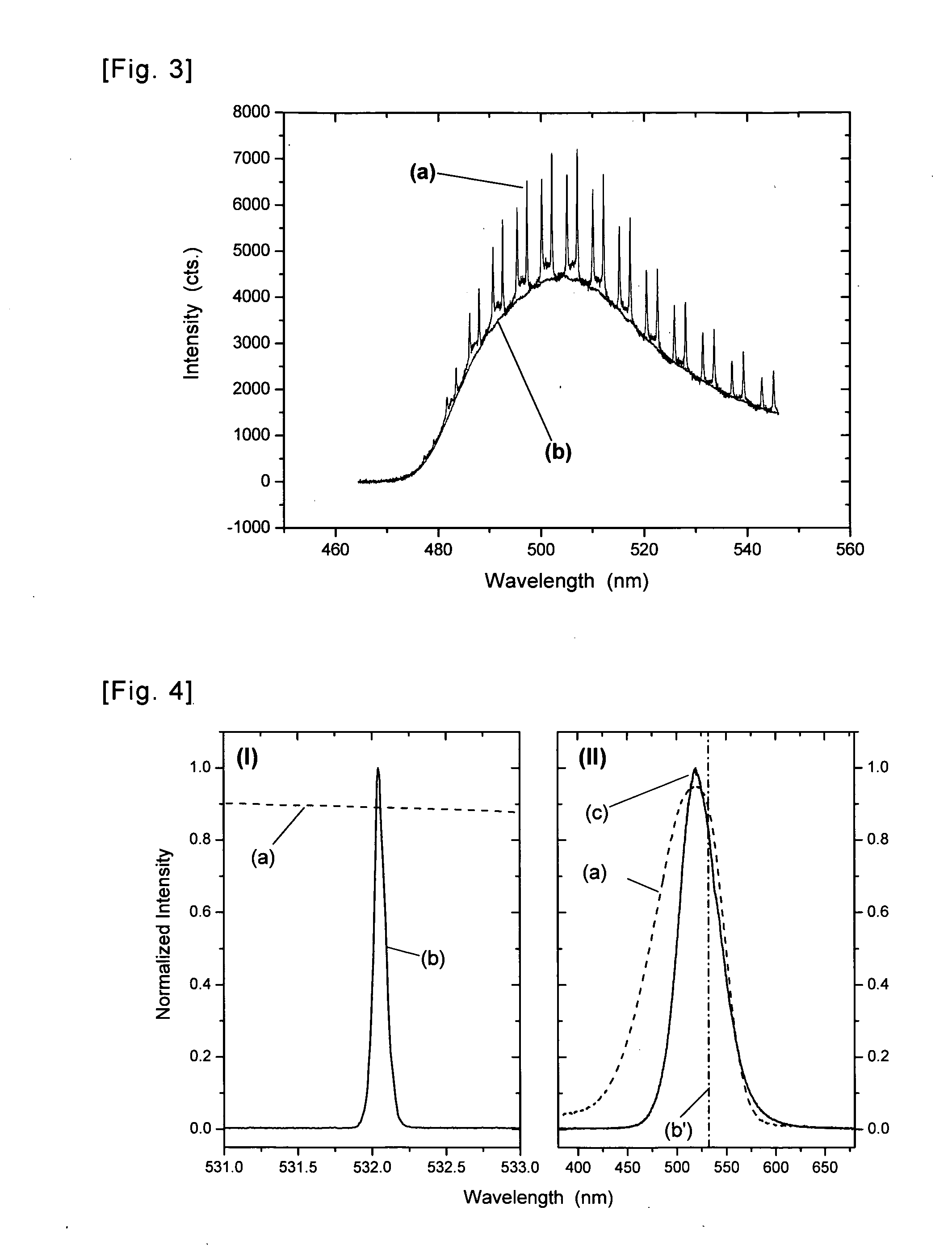
[0088]In this example, we demonstrate that optical cavity modes generated in fluorescent microresonators via excitation of the fluorescent material show an enhancement in the fluorescence emission spectra of the microresonator as compared to other, i.e. non-resonant, emission wavelengths.
[0089]Materials & Methods. A drop of suspension of C6G-doped PS microbeads (Polysciences, Inc., Warrington, Pa.) with a nominal diameter of 10 μm was placed on a glass microscopy cover slip. The sample was mounted onto the sample stage of a Nikon TS100 inverted microscope, which was used for observation and selection of suitable microbeads as well as their excitation and detection. For excitation, a cw-HeCd laser (Kimmon Lasers, Tokyo, Japan) operating at 442 nm was applied. The laser power at the microscope objective used for excitation and detection (Nikon, 100×) was 24.7 μW with a focus of about 20 μm. For detectio...
example 2
Comparison of Beam Characteristics of Laser and LED
[0091]In this example, the beam characteristics of the light sources used in Example 3 for excitation of WGM in fluorescently doped PS beads are compared.
[0092]The most important differences in the emission characteristics of the two sources with respect to the present embodiment are the emitted spectral range, coherence, and beam profile. While the laser (Lumera Lasers, Germany, model Rapid) emits a monochromatic, highly coherent beam with almost ideal Gaussian (TE00) profile, the LED (OptoSupply, Japan, model OSG3DA5111A-VW) sends out broadband, incoherent radiation with varying intensity distribution in different directions, yielding an irregular profile within the illuminated solid angle. These properties of LED emission make light collection, guidance, and in particular focusing a difficult task, not least because of the chromatic and spatial aberrations of optical systems typically used for such purpose. In contrast, the laser...
example 3
Comparison of Laser and LED as Excitation Sources for Generation of Optical Cavity Mode Spectra in Fluorescent Microresonators
[0097]In this example, optical cavity mode spectra obtained from fluorescent microresonators upon excitation with a laser and a LED, respectively, will be compared with each other.
[0098]Materials & Methods. A small droplet (˜10 μl) of suspension of Nile red-doped PS microbeads (Polysciences, Inc., Warrington, Pa.) with a nominal diameter of 15 μm was placed on a glass microscopy cover slip, laterally confined by means of a viton sealing, and covered with a piece of fused silica glass after the void volume had been filled with PBS buffer solution. The sample was attached to the Nikon inverted microscope as in Example 1. For WGM excitation, the two light sources discussed in detail in Example 2 were applied, which are (i) a Nd:YAG picosecond laser (Lumera Lasers, model Rapid) with a pulse repetition rate of 500 kHz and a pulse duration of 9 ps and (ii) a green ...
PUM
 Abstract
Description
Claims
Application Information