Monolithically integrated multi-wavelength high-contrast grating vcsel array

a monolithic integrated, high-contrast grating technology, applied in the direction of semiconductor lasers, laser details, electrical apparatus, etc., can solve the problems of difficult to achieve the precise control of the lasing wavelength using the above methods, large number of fabrication steps, and inability to scale for large vcsel arrays. achieve the effect of high reflectivity

Inactive Publication Date: 2012-05-24
RGT UNIV OF CALIFORNIA
View PDF2 Cites 49 Cited by
  • Summary
  • Abstract
  • Description
  • Claims
  • Application Information

AI Technical Summary

Benefits of technology

[0014]Multi-wavelength VCSEL array apparatus and fabrication methods are described which incorporate a high-contrast grating (HCG) as at least one of the mirrors in the VCSEL. It will be appreciated that the high reflectivity exhibited by HCGs over a broad wavelength range, for example Δλ/λ of approximately 35%, makes them an effective alternative to the use of conventional distributed-Bragg reflectors (DBR). Using these teachings, the lasing wavelength of the VCSEL can be controlled over a very broad range (e.g., greater than approximately 100 nm) by varying the duty cycle and the period of the HCG, such as throug

Problems solved by technology

The precise control of lasing wavelength using the above methods are very difficult to achieve due to the irregularity in temperature gradients in an MBE system and the complex fluid mechan

Method used


Image

  • Monolithically integrated multi-wavelength high-contrast grating vcsel array
  • Monolithically integrated multi-wavelength high-contrast grating vcsel array
  • Monolithically integrated multi-wavelength high-contrast grating vcsel array

Examples


embodiment 1

[0078]2. The apparatus , wherein said first mirror structure is fabricated over a substrate.

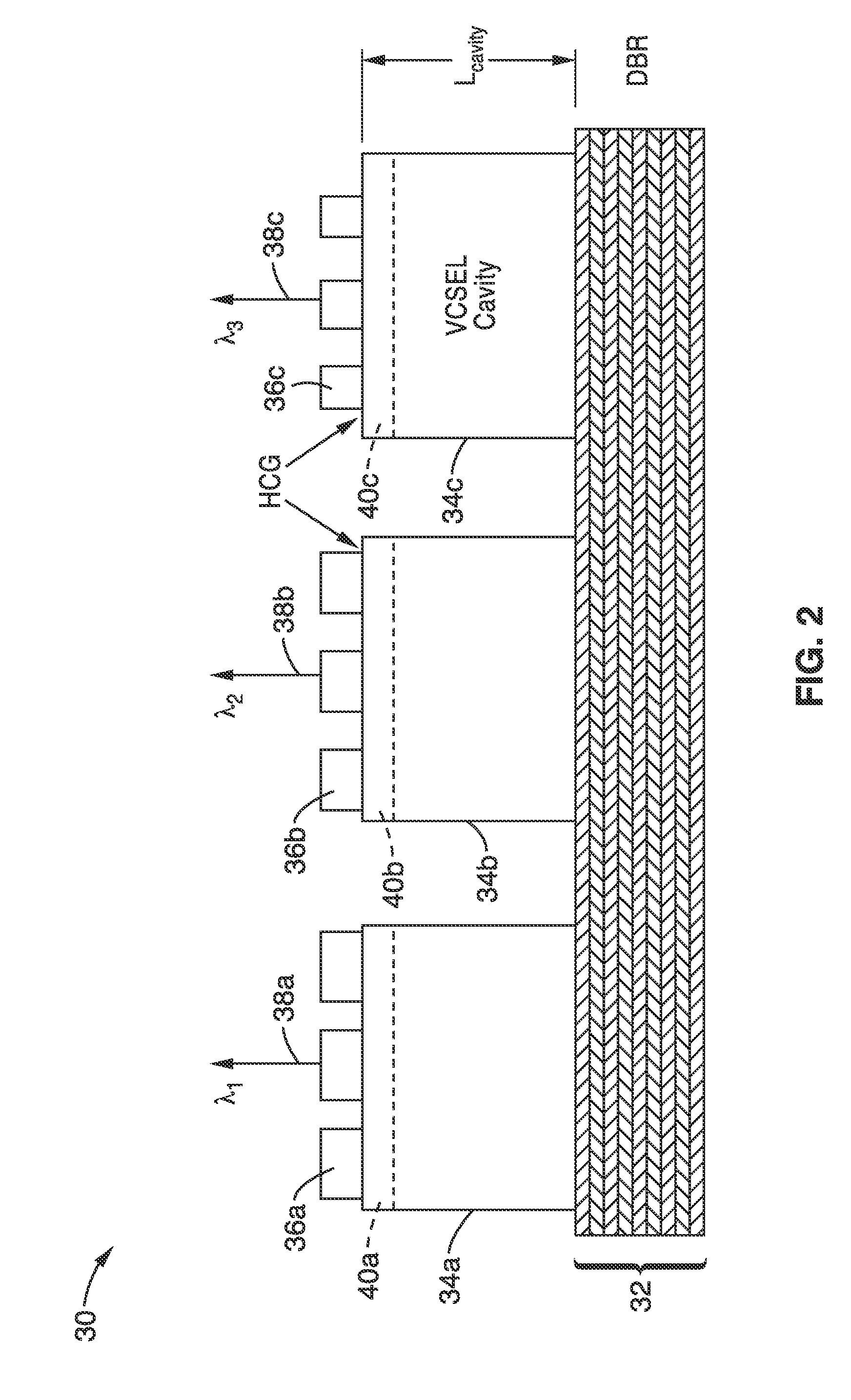
[0079]3. The apparatus according to embodiment 1, wherein said first mirror structure comprises a distributed Bragg reflector (DBR).

[0080]4. The apparatus according to embodiment 1, wherein said substrate comprises Indium Phosphide (InP), GaAs, GaN, sapphire or Si.

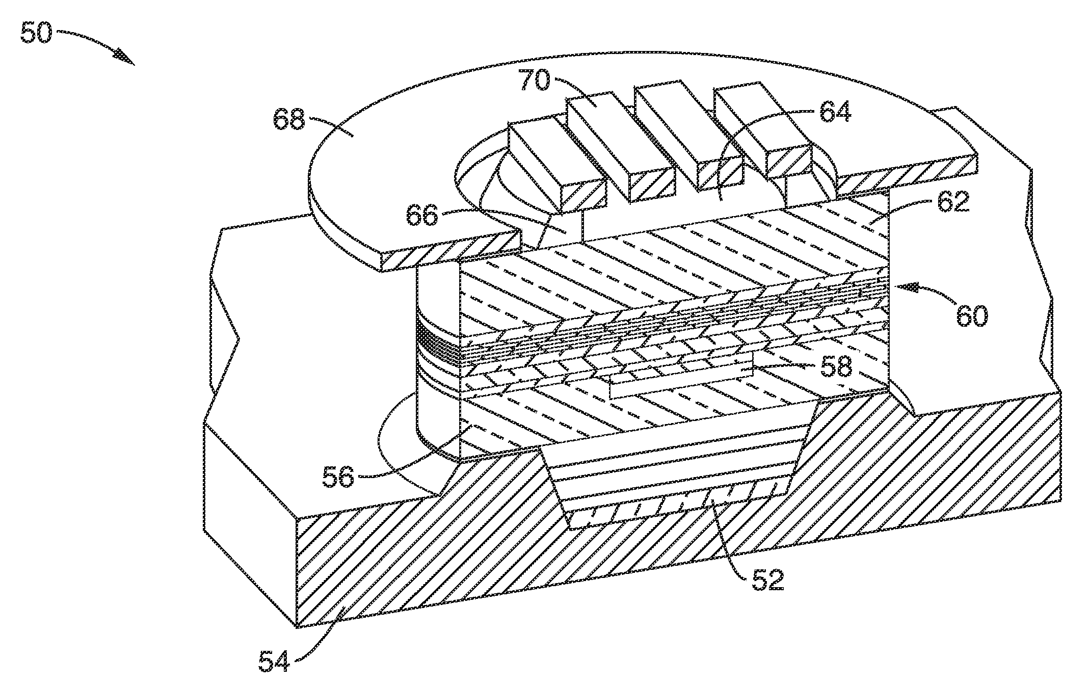
[0081]5. The apparatus according to embodiment 1, wherein said high-contrast grating (HCG) is configured for reflecting a first portion of the light back into each said vertical cavity at a controlled polarization, while a second portion of the light is output from said apparatus.

[0082]6. The apparatus according to embodiment 1, wherein each vertical cavity is configured with a tunnel junction for removing the majority of p-doped materials.

[0083]7. The apparatus according to embodiment 1, wherein said first mirror structure comprises a first mirror layer over which are disposed a plurality of vertical cavities.

[0084]8. The apparatus...

embodiment 11

[0088]12. The apparatus , wherein said electrical confinement layer comprises areas of ion implantation.

[0089]13. The apparatus according to embodiment 11, wherein said electrical confinement layer comprises a buried tunnel junction.

[0090]14. The apparatus according to embodiment 11, wherein said electrical confinement layer comprises an oxide aperture.

[0091]15. The apparatus according to embodiment 11 further comprising a vertical resonator cavity disposed over said electrical confinement layer.

[0092]16. The apparatus according to embodiment 1, further comprising an air gap disposed between said high-contrast grating (HCG) and each vertical cavity.

[0093]17. The apparatus according to embodiment 1, further comprising a low index material layer, with refractive index less than two, disposed between said high-contrast grating (HCG) and each vertical cavity.

[0094]18. The apparatus according to embodiment 1, wherein said high contrast grating comprises a material having a refractive ind...

embodiment 26

[0103]27. The method , wherein said first mirror comprises a Distributed Bragg Reflector (DBR) mirror, or another High Contrast Grating (HCG) mirror.

[0104]28. The method according to embodiment 26, further comprising the step of etching away a sacrificial layer from beneath said HCG of each of said second mirrors to form a sub-grating space of low index material.

[0105]29. The method according to embodiment 26, further comprising the step of fabricating an electrical confinement layer adjacent said active region.


PUM


Abstract

Multiple-wavelength VCSEL array apparatus and method having a high contrast grating (HCG) mirror which can be implemented on a single substrate in which only the dimensions of the HCG (e.g., duty cycle or the period) need be changed to alter the wavelength of a given VCSEL in response to changing the reflectivity phase of the HCG mirror. The HCG can be defined by any desired lithographic process. By using a broadband HCG mirror a large wavelength span over 100 nm is provided, such as covering the entire C-band. The HCG multi-wavelength VCSEL array enables single-transverse mode emission and polarization control and scalability with respect to wavelength.

Description

CROSS-REFERENCE TO RELATED APPLICATIONS[0001]This application a 35 U.S.C. §111(a) continuation of PCT international application number PCT / US2010 / 036103 filed on May 26, 2010, incorporated herein by reference in its entirety, which is a nonprovisional of U.S. provisional patent application Ser. No. 61 / 181,586 filed on May 27, 2009, incorporated herein by reference in its entirety. Priority is claimed to each of the foregoing applications.[0002]The above-referenced PCT international application was published as PCT International Publication No. WO 2010 / 138524 on Dec. 2, 2010 and republished on Mar. 31, 2011, and is incorporated herein by reference in its entirety.[0003]This application is related to U.S. patent application Ser. No. 12 / 779,248 filed on May 13, 2010, incorporated herein by reference in its entirety. This application is also related to PCT international patent application number PCT / US2010 / 034731 filed on May 13, 2010, incorporated herein by reference in its entirety.ST...

Claims


Application Information

Patent Timeline
IPC IPC(8): H01S5/343H01S5/183H01L21/02H01S5/187
CPCH01S5/0654H01S5/1221H01S5/1231H01S5/18308H01S5/18319H01S5/423H01S5/18358H01S5/18369H01S5/18386H01S5/4087H01S5/18355
Inventor CHANG-HASNAIN, CONNIEPESALA, BALA SUBRAHMANYAMKARAGODSKY, VADIM
Owner RGT UNIV OF CALIFORNIA
Why Eureka
Try Eureka