Operators of wireless networks face a number of challenges in cost-effectively deploying networks resources to meet recent dramatic increases in the demand for total
data capacity.
For example, in 2009, introduction of the iPhone® by one operator in the United States resulted in a sudden massive increase in the total
traffic volume, with
resultant stress on their network resources to provide the required
cell site capacity to satisfy increased user demand.
Although
cell splitting, with deployment of small cells, is an attractive option to increasing capacity, existing high capacity backhaul solutions depend on fibre and
microwave and are costly to implement.
Operators have limited options to meet the increasing capacity demand with existing network technologies.
The
disadvantage is that the additional carriers do not increase the Uplink speed since this is effectively limited by the
path loss of the
large cell and the limited energy per bit which a user terminal can generate.
Although the LTE technology is based on OFDM /
MIMO, the uplink performance at the
cell edge is not greatly increased, since this is still limited by the energy / bit that is required to compensate for the large
path loss and the limited power which a UE (
User Equipment?)
transmitter is able to generate.
Moreover, as operators roll out 4G networks, they are faced with a delicate balancing act.
They must invest heavily in infrastructure for a new
air interface knowing that the initial subscriber density will be very low and their investment will not create significant amounts of revenue for several years.
Most operators would expect their 4G investments to generate a net loss until a minimum subscriber density is achieved.
Although such a cautious deployment method makes sense, inter-operator competition for
footprint may force operators to be more aggressive, take more risk, and deploy 4G aggressively in an effort to
gain market share.
Two key challenges of
cell splitting are site acquisition and backhaul.
Considering site acquisition, for
macro-cells, the ability to cell split is restricted by the number of available towers or high-rise buildings.
Furthermore,
zoning laws may
restrict the ability to build new towers and in some jurisdictions even if they allow a new
tower to be built, obtaining a permit can take several years.
High capacity
fiber links are available on major
high rise buildings and on many cellular towers, but they are not available for the vast majority of utility poles where an operator may wish to deploy a
PicoCell.
Today, a 100 BaseT
Ethernet link can cost upwards of $1500 / month in the US and Canada, which results in very significant OPEX, costs ($18 k / year).
The complication is that
Microwave Radio operates at higher frequencies and as a result is restricted to
Line of Sight (LOS) type deployments.
This is not a major impediment for establishing a link between two elevated sites, which are substantially above the
clutter, but it is no longer an option when the PicoCells or Microcells are deployed on lower elevation structures, below
clutter, and LOS conditions no longer exist between the
PicoCell and a desired aggregation point.
On the other hand, there are a number of other challenges that arise in implementing a NLOS solution.
NLOS Radio Links operate at lower frequencies than LOS
Microwave Radio Links, and a larger
path loss is expected for a given propagation distance because the
signal must travel through obstructions such as buildings, trees, or around small hills.
Reduced directionality, the random nature of obstructions, fluctuating path losses and beam spreading increase the probability of co-channel interference.
Furthermore, the availability of spectrum at lower frequencies, which can be used to implement NLOS backhaul links is scare and as such the channel bandwidth is typically limited to 10 MHz or 20 MHz whereas for a
microwave link operating at higher frequencies, larger channel bandwidth of 40 Mhz or even 50 MHz are typical.
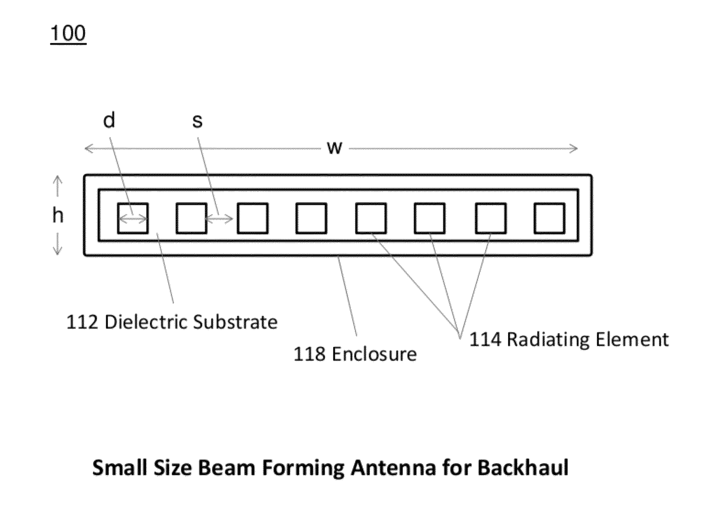
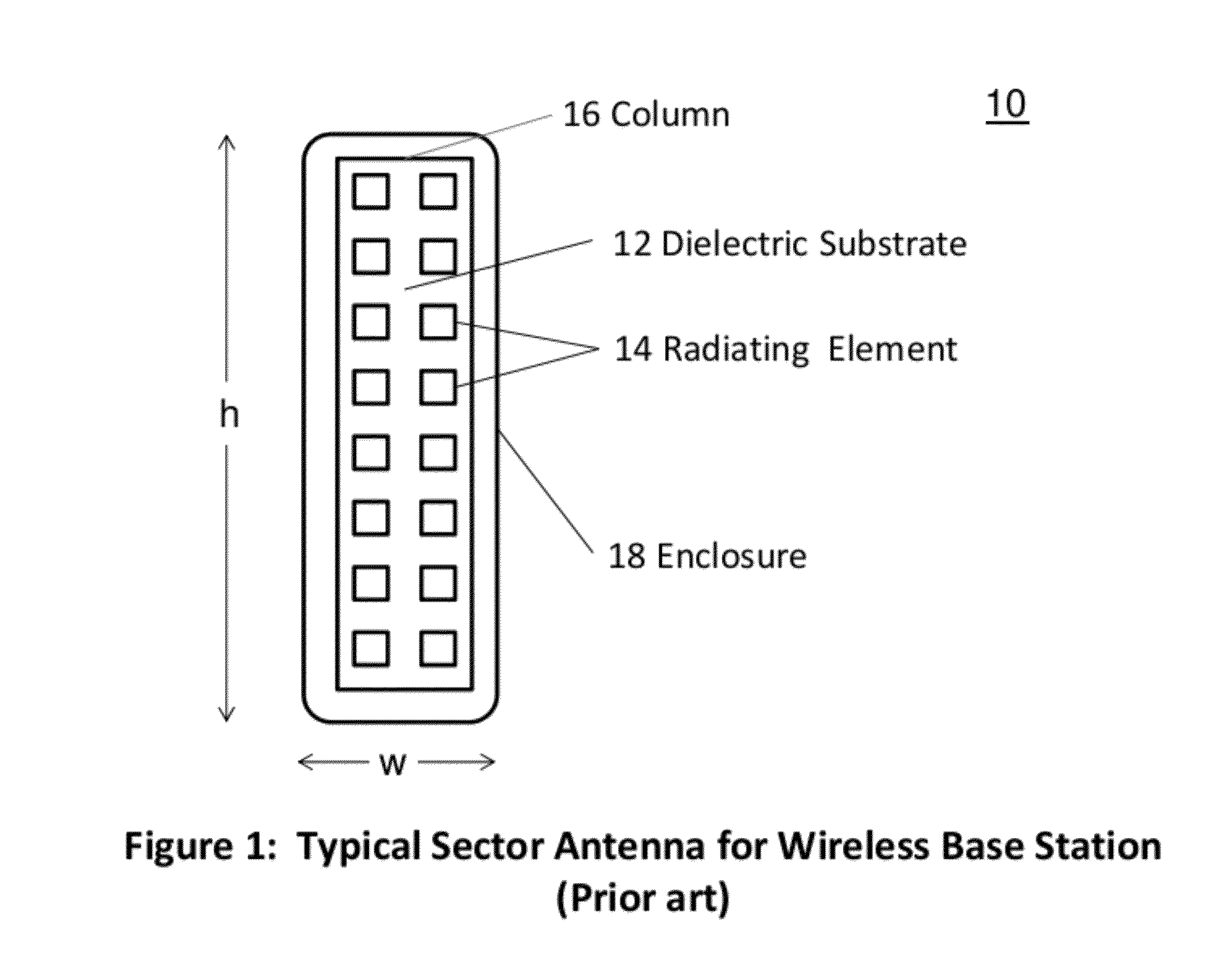
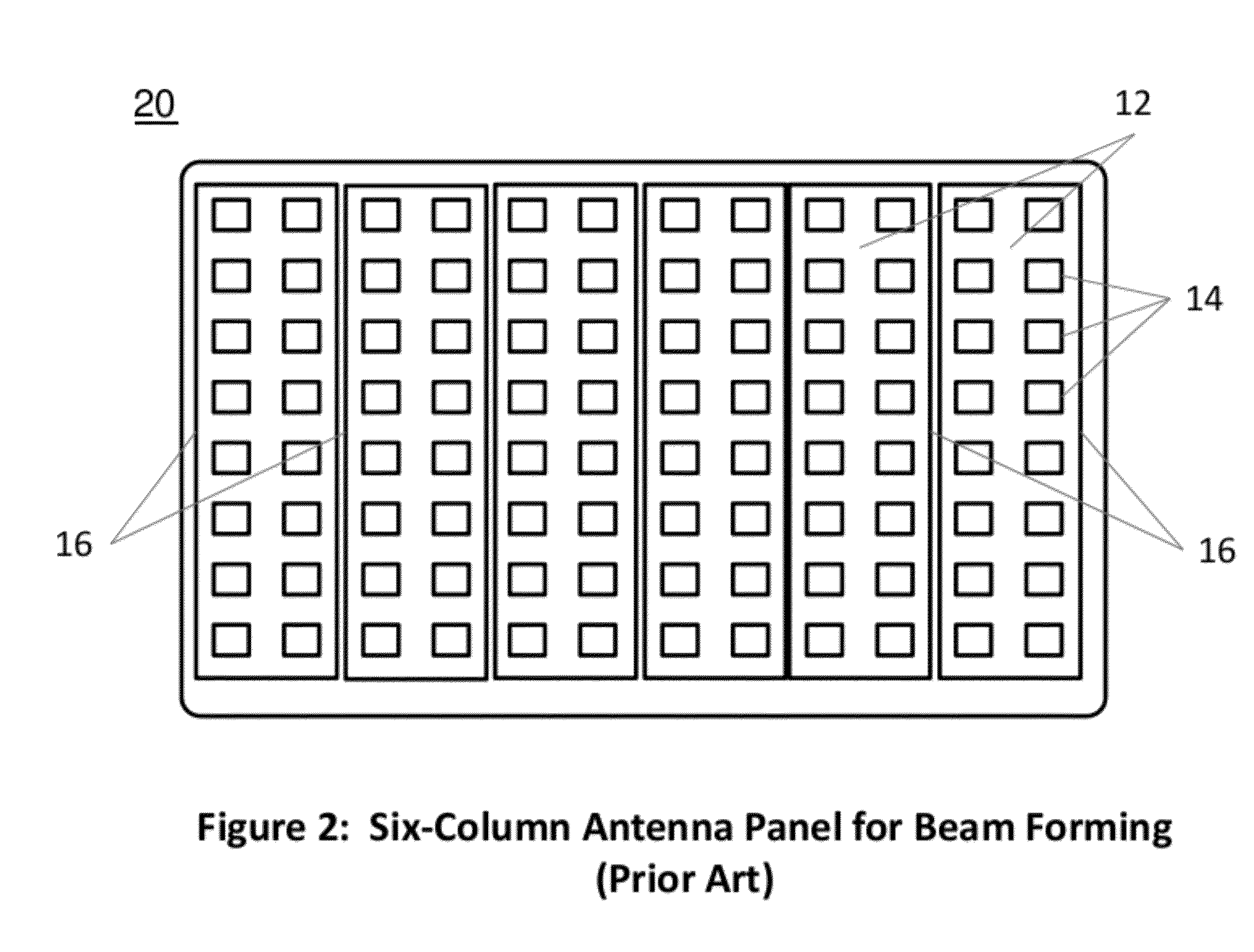
Beam forming has been the object of research and trials in 2G and 3G networks but has never seen widespread use due to deployment challenges.
One of the largest challenges has been the size of the antenna panel which is needed to create a multi-
beam system and the
resultant deployment issues.
a) The size of the antenna results in significantly more wind loading on the
tower than a
sector antenna. Cellular towers that were originally engineered to withstand a certain amount of wind loading may not be able to support this new larger antenna.
b) The large antenna is an eyesore and it is more difficult for operators to obtain a permit to deploy such a large antenna panel.
c) Historically there have been large and expensive RF cables between the
Base Station Transceiver which is on the ground and the antenna. Beam forming systems require a radio to be connected to each antenna column and hence there is a significant increase in the cost, size and weight of the RF cables.

