Scannable flip-flop with hold time improvements

a technology of hold time and flip-flop, which is applied in the direction of pulse generators, pulse techniques, electrical devices, etc., can solve the problems of performance penalty, impracticality or even impossible to test, etc., and achieve the effect of improving circuit performance and reducing data hold tim

Inactive Publication Date: 2012-06-14
APPLE INC
View PDF3 Cites 28 Cited by
  • Summary
  • Abstract
  • Description
  • Claims
  • Application Information

AI Technical Summary

Benefits of technology

[0008]Various embodiments of a scannable flip-flop are disclosed that may reduce data hold time, which may in turn improve the performance of circuits incorporating the scannable flip-flop. In an embodiment, the scannable flip-flop may include an input multiplexer, a master latch, and a slave latch. The multiplexer may include a number of input ports, such as a port coupled to receive normal operating mode data and a port...

Problems solved by technology

In some cases, scan-based testing may allow testing of circuit elements that might be impractical or even impossible to test through functi...

Method used


Image

  • Scannable flip-flop with hold time improvements
  • Scannable flip-flop with hold time improvements
  • Scannable flip-flop with hold time improvements

Examples


Embodiment Construction

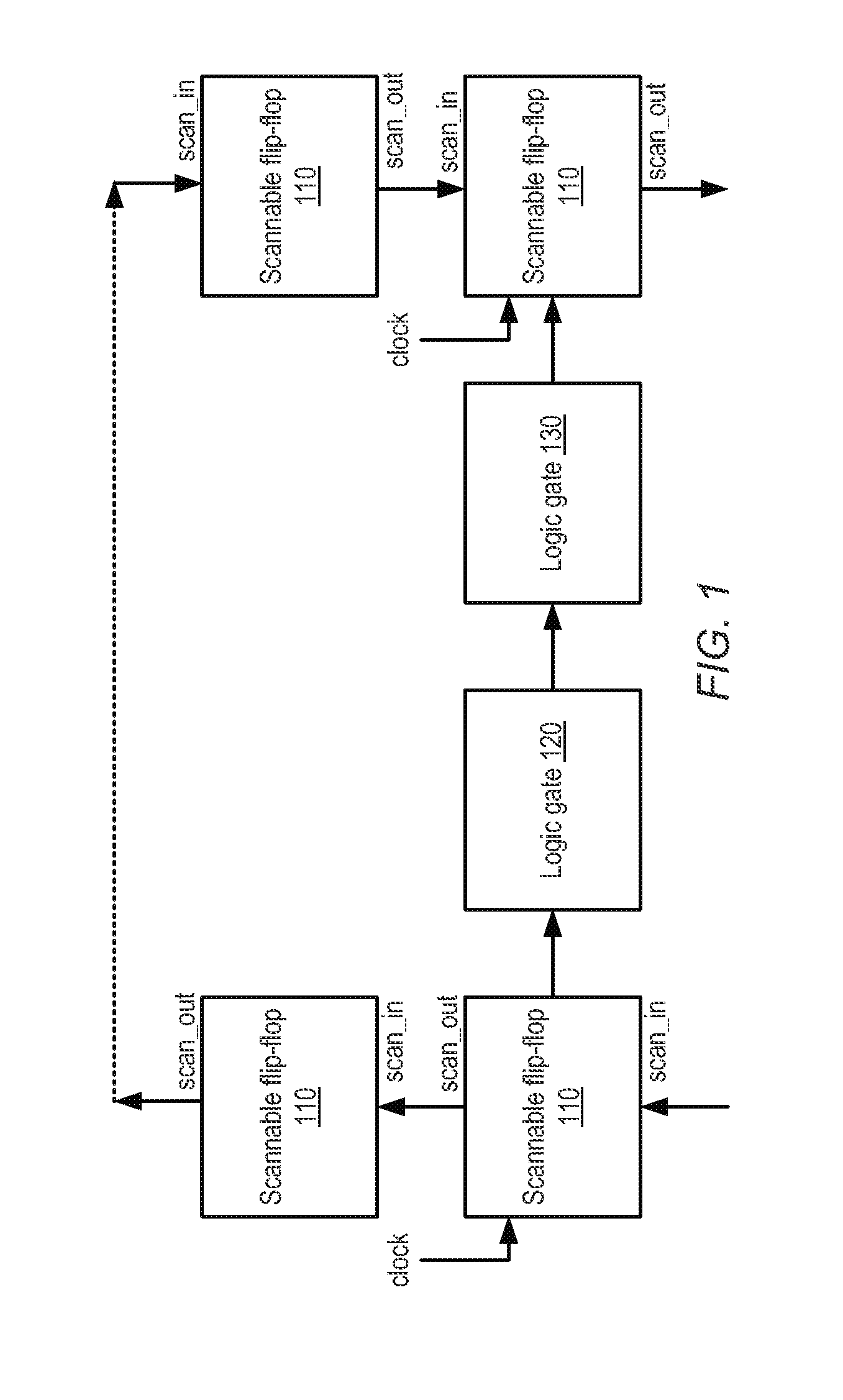
[0023]FIG. 1 illustrates an example of a portion of a scannable logic path. In the illustrated embodiment, scannable flip-flop 110 is coupled to a logic gate 120, which is in turn coupled to a logic gate 130. Logic gate 130 is coupled to another scannable flip-flop 110. Generally speaking, scannable flip-flop 110 may correspond to any suitable scannable state element, such as a static or dynamic flip-flop. Scannable flip-flop 110 may operate to capture and store input data in response to a clock signal. For example, scannable flip-flop 110 may be an edge-triggered state element.

[0024]Logic gates 120 and 130 may be configured to implement combinatorial logic functions of any suitable type (e.g., AND, OR, NAND, NOR, XOR, XNOR, or any suitable Boolean expression). Either of logic gates 120 or 130 may be implemented using static or dynamic logic. For example, if implemented using dynamic logic, gates 120 or 130 may also be clocked by a clock signal (not shown) that may be the same as or...


PUM


Abstract

Embodiments of a scannable flip-flop are disclosed that may reduce data hold time, which may in turn improve the performance of circuits incorporating the scannable flip-flop. The scannable flip-flop may include a slave latch and a master latch including an input multiplexer. The multiplexer may include a number of input ports, for example to receive normal operating mode data as well as scan operating mode data, and the multiplexer may be operable to controllably select one of the input ports and pass the value of the selected port to an output of the multiplexer. For example, the multiplexer may generate individual control signals for the various ports dependent upon both the clock signal and a select signal, such that each of the ports is qualified with the select signal and the clock signal before the multiplexer presents the input data of the selected port as the output of the multiplexer.

Description

PRIORITY CLAIM[0001]This application claims benefit of priority of U.S. Provisional Patent Appl. No. 61 / 422,605, filed Dec. 13, 2010, which is incorporated by reference herein in its entirety.BACKGROUND[0002]1. Technical Field[0003]This invention is related to the field of integrated circuit implementation, and more particularly to techniques for implementing scannable storage elements.[0004]2. Description of the Related Art[0005]Processors, and other types of integrated circuits, typically include a number of logic circuits composed of interconnected transistors fabricated on a semiconductor substrate. Such logic circuits may be constructed according to a number of different circuit design styles. For example, combinatorial logic may be implemented via a collection of unclocked static complementary metal-oxide semiconductor (CMOS) gates situated between clocked state devices such as flip-flops or latches. Alternatively, depending on design requirements, some combinatorial functions...

Claims


Application Information

Patent Timeline
IPC IPC(8): H03K3/289
CPCH03K3/35625H03K3/012
Inventor LEACH, DERRICK A.BEST, THOMAS J.MCCOMBS, EDWARD M.
Owner APPLE INC
Why Eureka
Try Eureka