Method for producing carbon nanotube assembly having high specific surface area

a carbon nanotube and assembly technology, applied in the direction of catalyst activation/preparation, physical/chemical process catalysts, metal/metal-oxide/metal-hydroxide catalysts, etc., can solve the problem of reducing the efficiency of cnt growth, preventing efficient cnt growth, and the method is also problematic in terms of cost, so as to suppress the generation of carbon impurities, reduce feedstock gas waste, and increase the effect of carbon efficiency

Inactive Publication Date: 2012-06-14
NAT INST OF ADVANCED IND SCI & TECH
View PDF10 Cites 32 Cited by
  • Summary
  • Abstract
  • Description
  • Claims
  • Application Information

AI Technical Summary

Benefits of technology

[0044]The method of the present invention enables CNT assembly production in higher carbon efficiency than in the conventional technique while suppressing carbon impurity generation. This makes it possible to greatly reduce feedstock gas wastes, and to easily produce a CNT assembly both stably and continuously. The CNT assembly so produced has a high specific surface area with the individual CNTs orderly aligned, and is readily moldable because of low weight density. The method therefore has good potential in industrial applications.

Problems solved by technology

With the conventional chemical vapor deposition method, however, the carbon impurities that generate during the synthesis of CNT cover the catalyst particles and easily deactivate the catalyst, preventing efficient CNT growth.
Increasing the carbon concentration using a conventional synthesis method deactivates the catalyst even more easily, and further lowers the CNT growth efficiency.
The method is also problematic in terms of cost, because the carbon efficiency which is a proportion actually converted into CNT from the carbon contained in the feedstock gas that has been in contact with the catalyst on a base in the growth step, is notably poor, and the most of the feedstock gas is wasted.

Method used


Image

  • Method for producing carbon nanotube assembly having high specific surface area
  • Method for producing carbon nanotube assembly having high specific surface area
  • Method for producing carbon nanotube assembly having high specific surface area

Examples


example 1

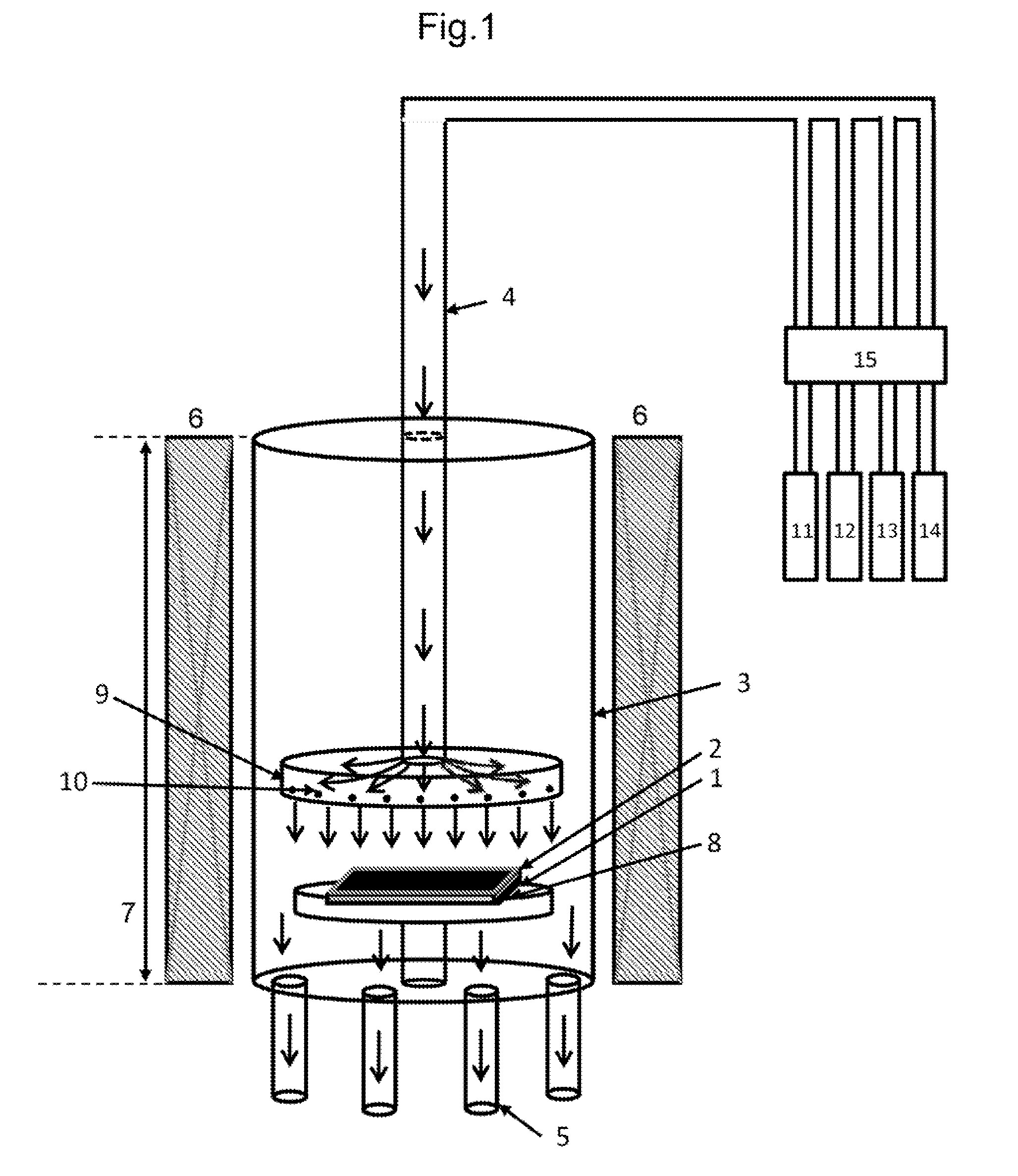
[0167]A CNT assembly was produced by using the CNT producing apparatus shown in FIG. 1, and a method similar to the CNT producing method described in the Best Mode. Descriptions will be given with reference to FIG. 1.

[0168]A quartz tube (inner diameter, 80 mm) such as a cylinder was used as the vertical synthesis furnace 3. The heating means 6 and the heating region 7 had a length of 260 mm.

[0169]A base holder 8 made of quartz was provided 50 mm downstream from a horizontal position at the center of the heating region 7. The base holder 8 was horizontally installed to allow a flat base 1 to be placed thereon.

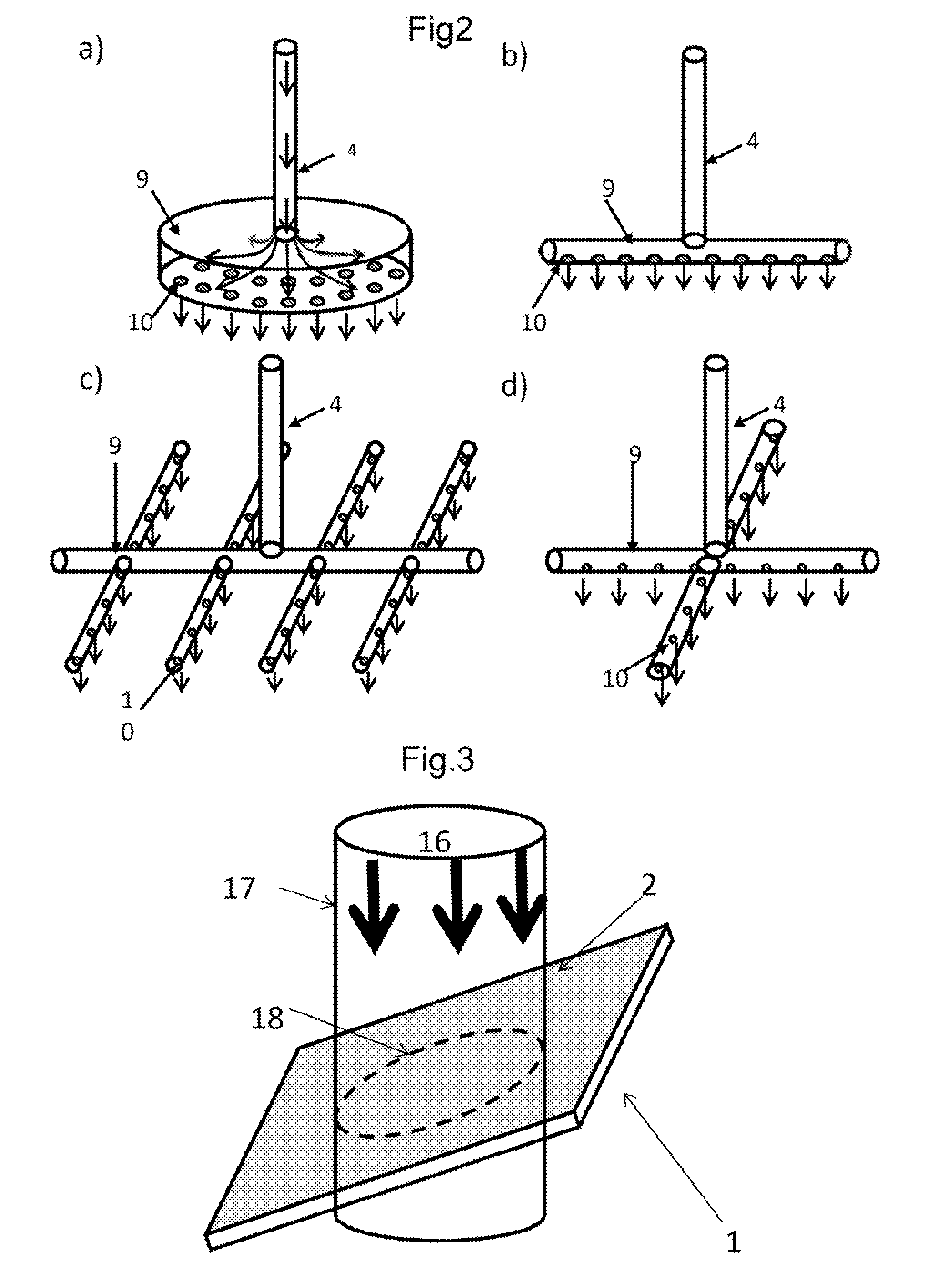
[0170]A gas supply pipe 4 made of a heat-resistant alloy and having a diameter of 22 mm (inner diameter, 20 mm) was provided through the upper wall of the synthesis furnace 3 by being vertically inserted through an opening provided through the upper wall of the synthesis furnace 3. The gas exhaust pipes 5 were provided through the bottom wall by being vertically inserted through...

example 2

[No Carbon Impurity Adhesion Suppressing Step]

[0198]A CNT assembly was synthesized according to the producing method of Example 1, using the same producing apparatus, base, and catalyst used in Example 1, without performing the carbon impurity adhesion suppressing step. The CNT assembly was immediately taken out of the heating region 7 after the synthesis. The CNT assembly grew, and had a specific surface area of about 900 m2 / g.

[0199]The yield remained unchanged during the 50 runs of continuous CNT assembly production. However, the specific surface area gradually decreased after 20 runs, and had a value of 800 m2 / g or less after 30 runs.

example 3

[No Gas Flow Forming Means]

[0200]In the producing apparatus of Example 1, the feedstock gas was blown onto the catalyst on the base 1 through the gas supply pipe 4 disposed 20 mm above the base 1, without using the gas flow forming means 9. The CNT assembly growth was uneven at the central portion and the peripheral portion of the catalyst layer 2 on the base 1, and the CNT assembly synthesized on the whole surface of the catalyst layer was slightly non-uniform. The yield was 0.4 mg / cm2, and the specific surface area was about 1,100 m2 / g. There were no fluctuations both in yield and specific surface area during the continuous production.


PUM

PropertyMeasurementUnit
diameteraaaaaaaaaa
temperatureaaaaaaaaaa
heightaaaaaaaaaa

Abstract

Disclosed is a method for continuously and stably producing a CNT assembly having a high specific surface area in a catalyst activating substance-containing, high-carbon-concentration environment.
Specifically disclosed is a method for growing a carbon nanotube by contacting a feedstock gas and a catalyst-activating substance to a catalyst on a base. The method includes: a formation step of supplying and contacting a reducing gas to the catalyst on the base, and heating at least one of the catalyst and the reducing gas to reduce the catalyst and/or particulate the catalyst; and a carbon nanotube growing step of contacting a carbon-containing, oxygen-free feedstock gas and an oxygen-containing catalyst-activating substance to at least one of the catalyst and the catalyst particles, and heating at least one of the catalyst, the catalyst particles, the feedstock gas, and the catalyst-activating substance to grow the carbon nanotube, wherein the ratio of the number concentration of the carbon atoms contained in the feedstock gas used in the carbon nanotube growing step to the number concentration of the oxygen atoms contained in the catalyst-activating substance used in the carbon nanotube growing step ranges from 0.5 to 200.

Description

TECHNICAL FIELD[0001]The present invention relates to a method for efficiently producing an aligned single-walled CNT assembly of a high specific surface area continuously from a high-carbon-environment, catalyst activating substance-containing feedstock.BACKGROUND ART [0002]There are high expectations for the development of carbon nanotubes (hereinafter, also referred to as “CNTs”) in functional new materials such as in electronic device materials, optical element materials, conductive materials, and bio-related materials. To this end, carbon nanotubes have been studied from various angles, including use, quality, and mass producibility.[0003]One known CNT producing method is the chemical vapor deposition method (hereinafter, also referred to as “CVD method”; see, for example, Patent Document 1). The method is characterized by contacting a feedstock gas such as a carbon compound with particles of catalyst in a high temperature atmosphere of about 500° C. to 1,000° C., and enables C...

Claims


Application Information

Patent Timeline
Patent Type & Authority Applications(United States)
IPC IPC(8): D01F9/127B82B1/00B82B3/00
CPCB01J23/74B01J23/745B01J37/16C01B2202/32B82Y30/00B82Y40/00C01B31/0233B01J37/347C01B32/162
Inventor HATA, KENJIFUTABA, DON N.YUMURA, MOTOO
Owner NAT INST OF ADVANCED IND SCI & TECH
Why Eureka
Try Eureka