Infrared detector based on suspended bolometric micro-plates

a technology of bolometric micro-plates and infrared detection, which is applied in the field of terahertz bolometric detection, can solve the problems of poor fill factor, higher cost, and inability to achieve satisfactory fill factor

Inactive Publication Date: 2012-06-21
COMMISSARIAT A LENERGIE ATOMIQUE ET AUX ENERGIES ALTERNATIVES
View PDF4 Cites 7 Cited by
  • Summary
  • Abstract
  • Description
  • Claims
  • Application Information

AI Technical Summary

Benefits of technology

[0037]In one embodiment of the invention, the metallic membrane is supported by a structure that rests on the support arms of the micro-plate; this reduces the overall dimensions of the structure that supports the metallic membrane.

Problems solved by technology

It is also well known that the physical principles used by these two types of detection are fundamentally different and that each have their own problems.
Although an architecture based on suspended micro-plates has many advantages, especially the possibility of being used without being cooled down to extremely low temperatures, the presence of the support arms of the bolometric micro-plates makes it impossible to achieve a satisfactory fill factor using current fabrication techniques—the more the micro-plates are miniaturized, the worse the fill factor becomes.
Nevertheless, these solutions make manufacturing processes more complex and involve higher costs.
This results in a complex manufacturing process which poses a risk to electrical continuity from one stage of the detector to another; this continuity is, however, a crucial element for ensuring optimal operation of the detector.
In addition, the presence of the electrical interconnection element that is in contact with the absorption stage can have an adverse impact on the absorption quality and sensitivity of the detector.
However, the space that must be left between each micro-plate in order to support the caps results in a significant reduction in the optically active surface area of the detector for any given array size and hence a direct drop in the efficiency of the detector.
By virtue of its construction, the useful surface area of a bolometric micro-plate that is suspended by support arms and dedicated to detecting infrared or terahertz radiation is limited compared with the surface area of the substrate and this reduces the detector's sensitivity.

Method used


Image

  • Infrared detector based on suspended bolometric micro-plates
  • Infrared detector based on suspended bolometric micro-plates
  • Infrared detector based on suspended bolometric micro-plates

Examples


first embodiment

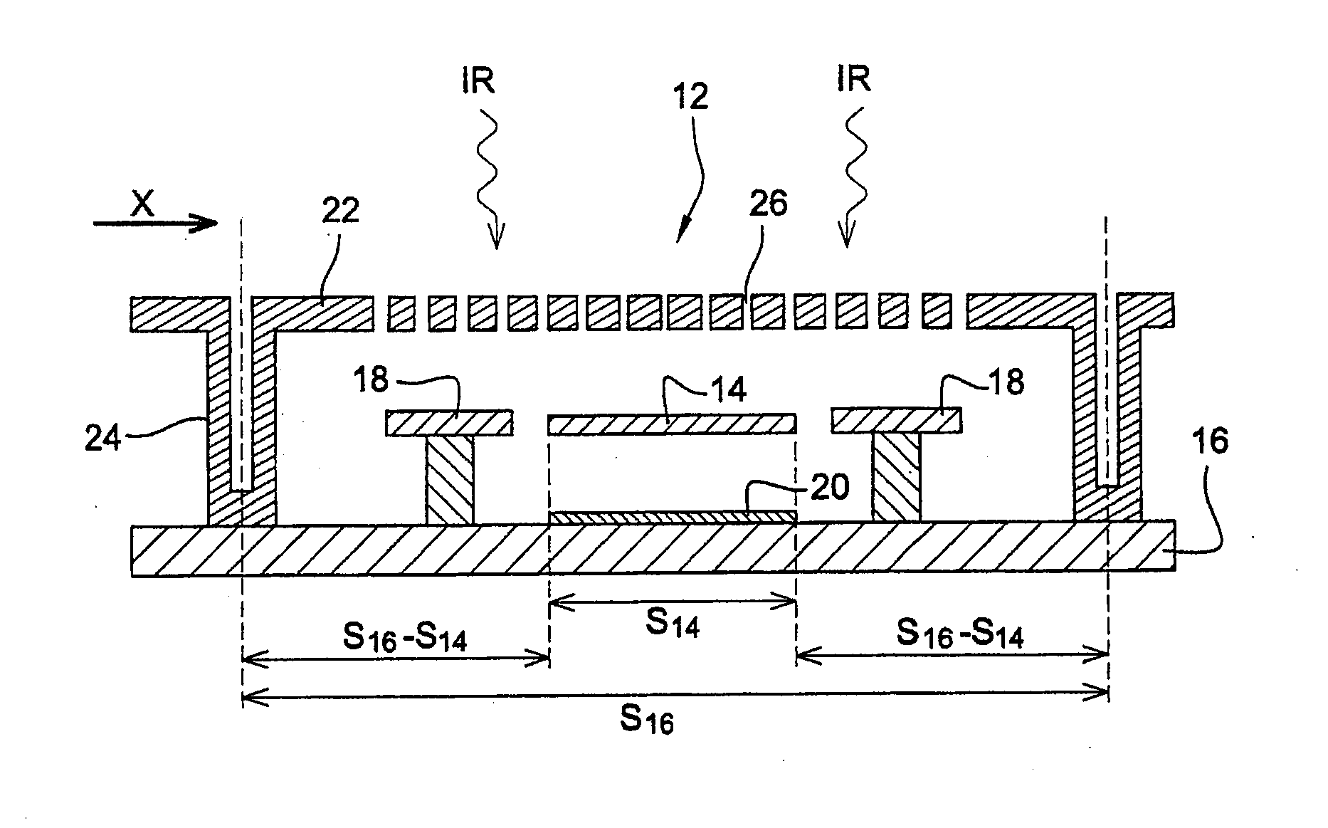
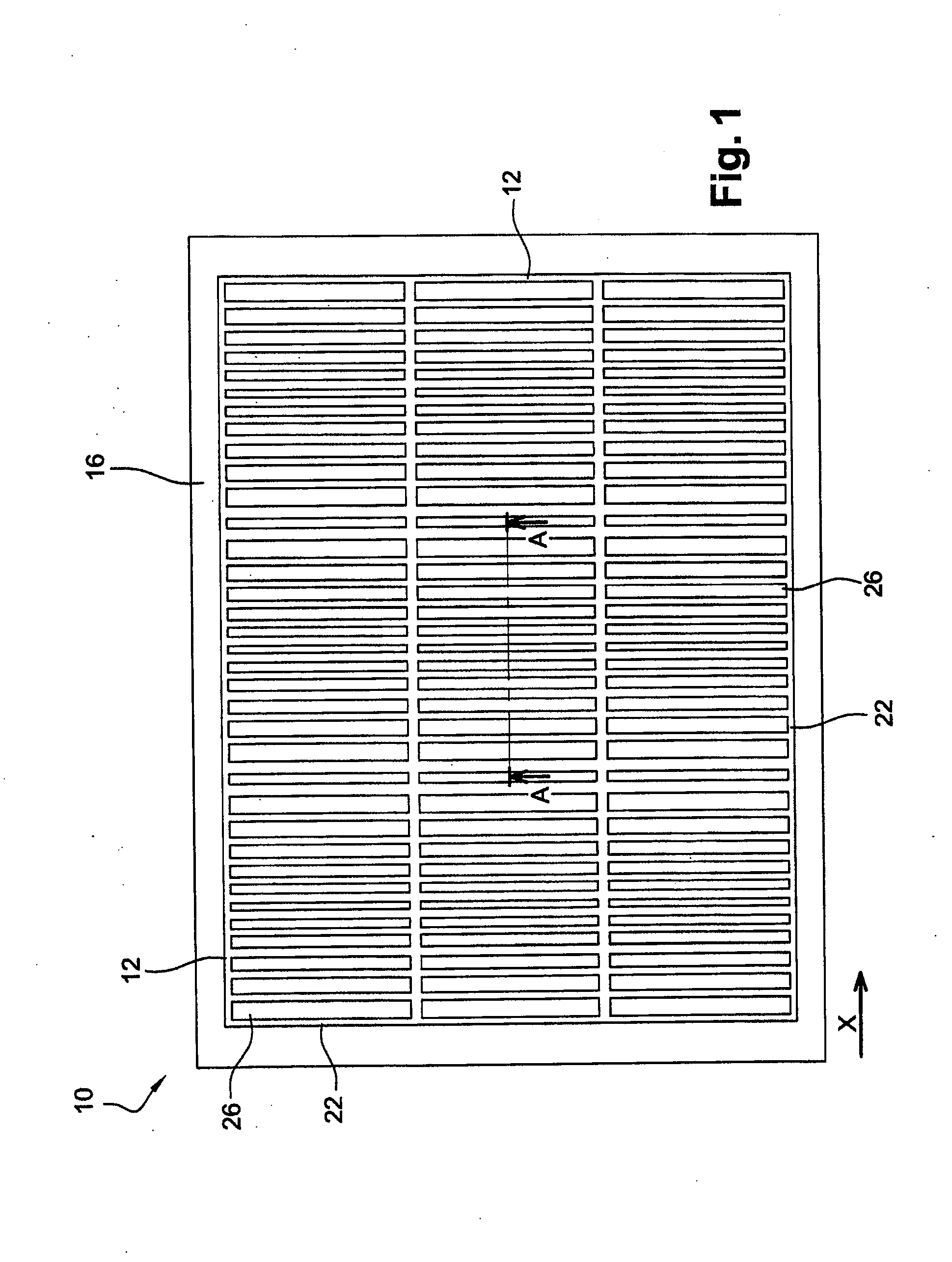
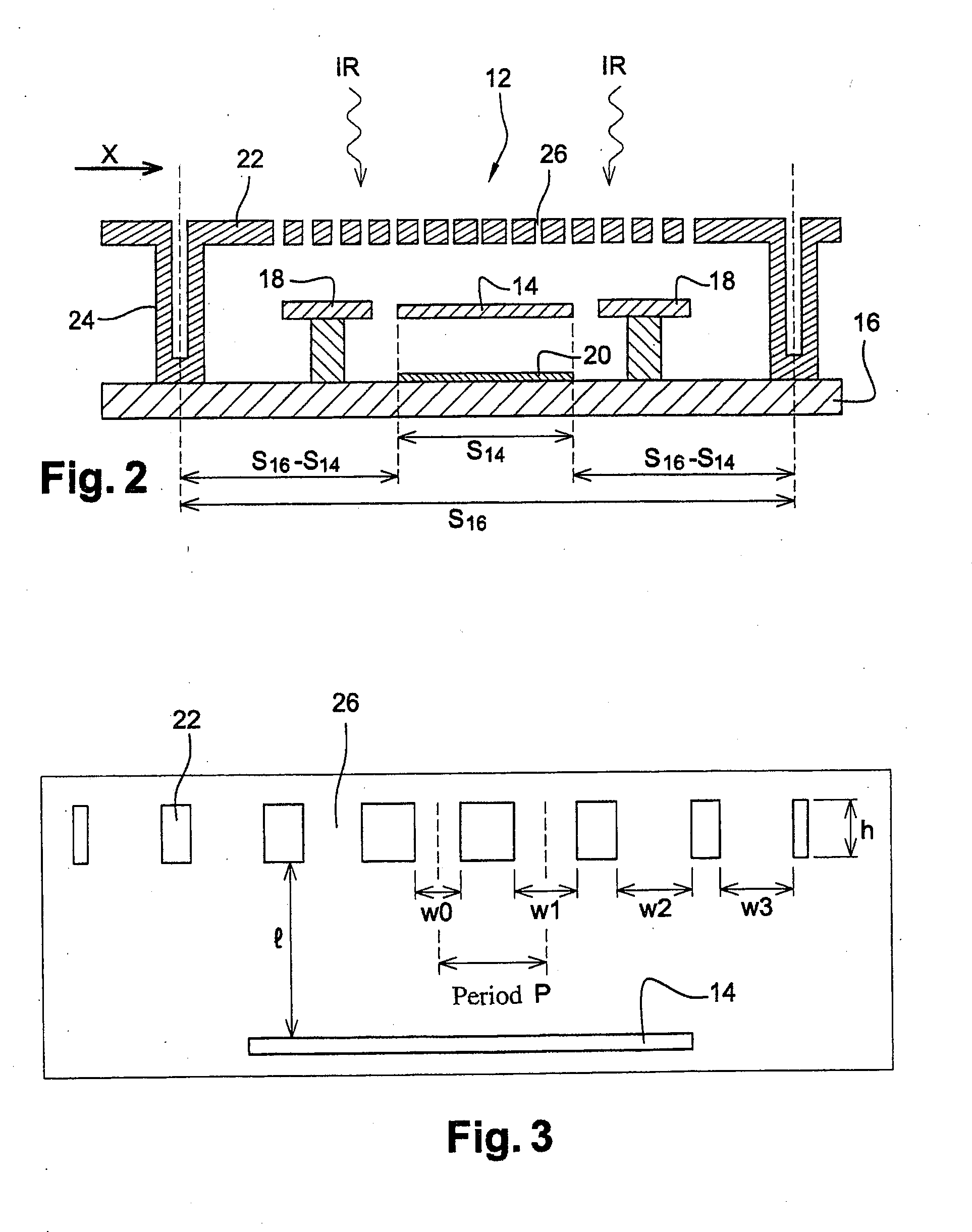
[0053]FIGS. 1 and 2 show, by way of example, a bolometric detector array 10 comprising three pixels by three pixels in accordance with the invention.

[0054]Each pixel 12 comprises a bolometric micro-plate 14, suspended above a substrate 16 by support and thermal isolation arms 18, which makes it possible to detect incident electromagnetic radiation IR in an infrared wavelength range from 0.75 μm to 1,000 μm and / or in a terahertz wavelength range from 1 mm to 3 mm.

[0055]As is known in itself, micro-plate 14 warms up due to the effect of the incident radiation IR and its electrical resistance varies as a function of the increase in its temperature. The same material can be used to implement both these functions, TiN for instance is suitable for detecting wavelengths in the mid infrared range.

[0056]The support and thermal isolation arms 18 consist mostly of a material with a low thermal conductance which contains an electrical conductor element that makes it possible to subject micro-pl...

second embodiment

[0097]the support structure and its manufacturing process are described below in relation to the schematic, cross-sectional views in FIGS. 13 to 15.

[0098]This method starts with the same steps as those described in relation to FIGS. 7 to 9 and then continues by depositing a solid sheet of a semiconductor or dielectric material so that sacrificial layer 44 and cuts 46 are covered by a layer 50 of said material (FIG. 13). However, unlike the previous embodiment, the thickness of the second sacrificial layer 42 deposited on micro-plate 14 takes into account the thickness of layer 50, with the sum of the thicknesses of layer 42 and layer 50 equaling the desired distance l between focusing membrane 22 and micro-plate 14.

[0099]The material of layer 50 is advantageously chosen so that it is compatible with the material of substrate 16, especially in terms of adhesion and deposition conformity.

[0100]The material of layer 50 is also chosen so that it is relatively non-absorbent in the wavele...


PUM


Abstract

This bolometric array detector for detecting electromagnetic radiation in a predetermined range of infrared or terahertz wavelengths comprises a substrate and an array of bolometric micro-plates for detecting said radiation that are suspended above the substrate by support arms. It comprises a metallic membrane located above and around each micro-plate and in which openings are formed; said openings in metallic membrane are periodically located in it along at least one predetermined axis with a period equal to or less than
λn,
where λ is a wavelength in the wavelength range that is to be detected and n is the average refraction index of the medium that separates the micro-plate from metallic membrane.

Description

FIELD OF THE INVENTION[0001]The invention relates to the field of infrared and terahertz bolometric detection and, more especially, the field of bolometric detection using an array of micro-plates that are suspended above a substrate.BACKGROUND OF THE INVENTION[0002]It is frequently acknowledged that infrared detection, i.e. detection in the wavelength range from 0.75 μm to 1,000 μm, is a technological field that is fraught with particular problems. In fact, every object emits in the infrared spectrum as soon as its temperature exceeds 0° K. Thus, if an infrared detector is not cooled, the devices that surround the sensitive elements (substrates, connectors and wiring, packages, optics, etc.) emit significant infrared radiation which is added to the radiation originating from the scene that one is attempting to detect. This unwanted component can be very considerable and sometimes constitutes more than 99% of the total signal produced by the detection elements at a temperature of 30...

Claims


Application Information

Patent Timeline
Patent Type & Authority Applications(United States)
IPC IPC(8): G01J5/02
CPCB82Y20/00G01J5/02G01J5/023G01J5/024G01J5/08G02B2207/101G01J5/0806G01J5/0815G01J5/20G02B5/1809G02B5/1885G01J5/0803
Inventor DUMONT, GEOFFROYARNAUD, AGNESBOUTAMI, SALIMIMPERINETTI, PIERREMARY, ALEXANDREPOCAS, STEPHANERABAUD, WILFRIED
Owner COMMISSARIAT A LENERGIE ATOMIQUE ET AUX ENERGIES ALTERNATIVES
Why Eureka
Try Eureka