Switching voltage regulators with hysteretic control for enhanced mode-transition speed and stability

a voltage regulator and hysteretic control technology, applied in the direction of power conversion systems, dc-dc conversion, instant pulse delivery arrangements, etc., can solve the problem of slow transition between these operational modes, and achieve the effect of improving the speed and stability of the mode transition

Active Publication Date: 2012-06-28
ANALOG DEVICES INC
View PDF7 Cites 52 Cited by
  • Summary
  • Abstract
  • Description
  • Claims
  • Application Information

AI Technical Summary

Problems solved by technology

It has been found, however, that transitioning between these operational modes is slow, is sensitive to transient noise signals, and, often prone to circuit instabilities.

Method used


Image

  • Switching voltage regulators with hysteretic control for enhanced mode-transition speed and stability
  • Switching voltage regulators with hysteretic control for enhanced mode-transition speed and stability
  • Switching voltage regulators with hysteretic control for enhanced mode-transition speed and stability

Examples


embodiment 20

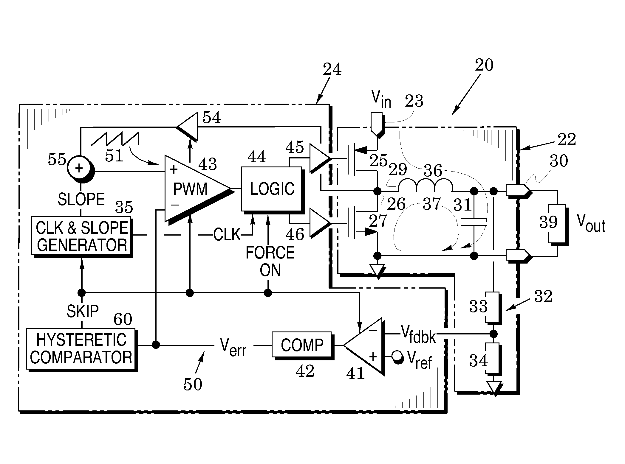
[0015]In particular, FIG. 1 illustrates a switching voltage regulator embodiment 20 that comprises an output stage 22 and a feedback controller 24. The output stage includes a first transistor 25 coupled between an input port 23 and a swinging node 26, a second transistor 27 coupled between the swinging node and circuit ground, and an inductor 29 coupled between the swinging node 26 and an output port 30. A capacitor 31 is coupled across the output port and a voltage divider 32 is coupled to the top of the output port. The voltage divider is formed by first and second impedances such as first and second resistors 33 and 34. In a regulator embodiment, the transistors may be metal-oxide-semiconductor, field effect (MOSFET) transistors and, if so, the drains of the transistors are preferably coupled to the swinging node 26.

[0016]The output stage 22 operates at a clock rate determined by a clock signal (CLK) from a clock and slope generator 35. In operation of the output stage 22, the f...

embodiment 80

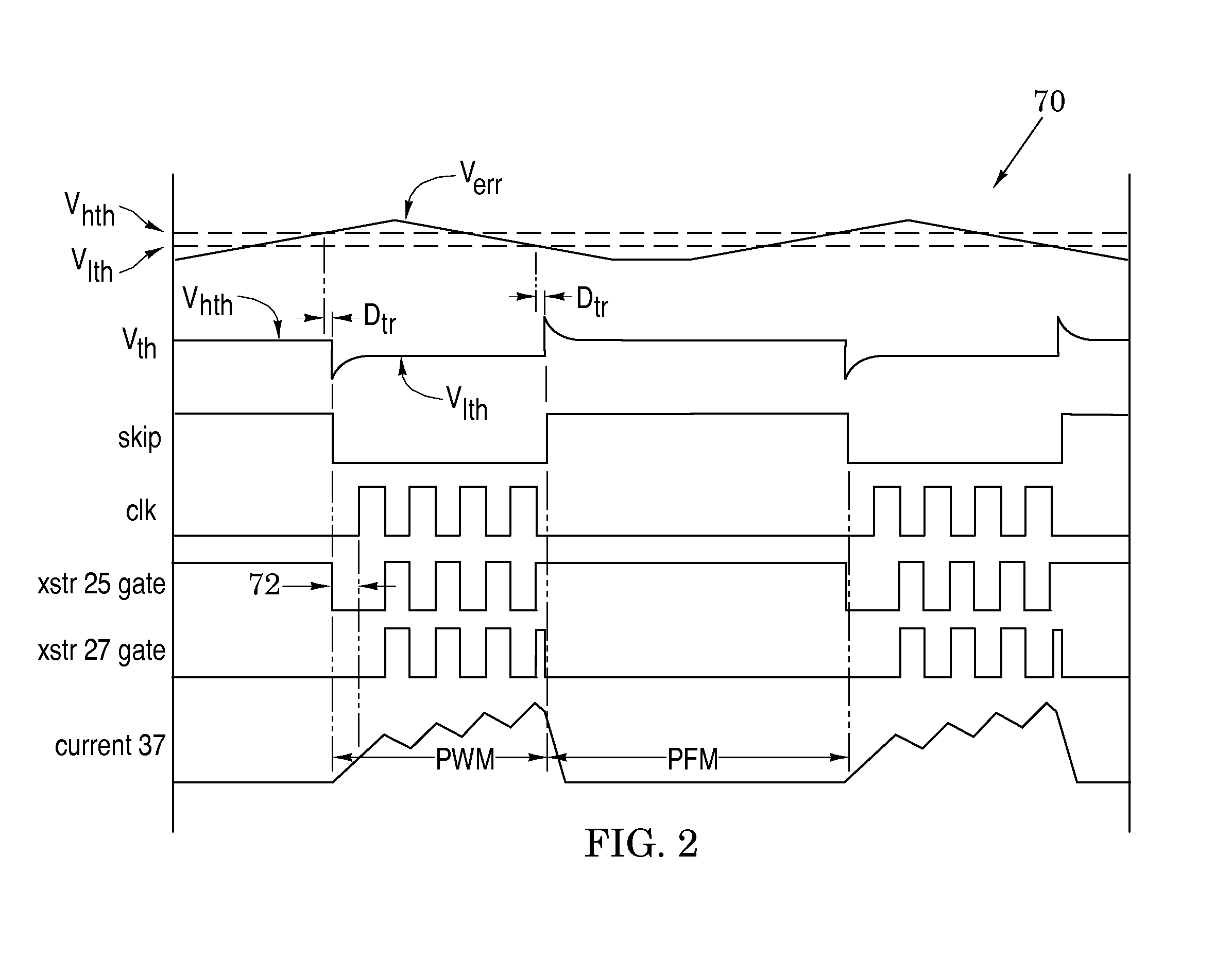
[0028]The graph 70 of FIG. 2 illustrates various waveforms in the voltage regulator 20 as it transitions between its PWM and PFM operational modes. Before describing the operations of this graph, however, it will be instructive to first describe operation of the hysteretic comparator 60. Accordingly, attention is now directed to FIG. 3A which illustrates a hysteretic comparator embodiment 80. As shown, it includes a comparator 81 which drives an inverter 82 to generate the skip signal of FIG. 1. A first switch 84 is arranged to couple a high threshold voltage Vhth to the negative input of the comparator 81 and this first switch is closed when the output of the inverter 82 is high. A second switch 85 is arranged to couple a low threshold voltage Vhth to the negative input of the comparator and this second switch is closed when the output of the comparator 81 is high. Finally, a capacitor 86 is coupled from the output of the inverter 82 back to a summer 87 positioned between the switc...

embodiment 90

[0035]FIG. 3C illustrates another embodiment 90 of the hysteretic comparator. In this embodiment, a differential amplifier 92 is formed by a differential pair 93 of transistors 94 and 95 that are positioned to receive a tail current from a current transistor 96 (biased by a tail voltage Vt) and drive load transistors 97 and 98 that are biased by a first bias voltage Vb1. The transistor 95 receives a low threshold voltage Vlth at its gate. A diode-coupled transistor 100 is drain-coupled to a current transistor 101 whose source is coupled to one side of the differential pair 93 and whose gate is coupled to a second bias voltage Vb2. Another transistor 102 is gate-coupled to the transistor 100 and drain-coupled to a current transistor 103 whose source is coupled to the other side of the differential pair 93 and whose base is coupled to the second bias voltage Vb2.

[0036]A current transistor 106 has its gate coupled to receive the first bias voltage Vb1 and is drain-coupled to a transist...


PUM


Abstract

Switching voltage regulator embodiments are provided with hysteretic control to thereby switch between pulse-width modulation and pulse-frequency modulation operational modes. The switching is in response to different levels of an error voltage Verr in the feedback loop of voltage regulators. The hysteretic control is configured to provide a dc hysteretic response to changes in the error voltage Verr and also an ac hysteretic response to these changes. These two responses can be independently set to thereby enhance operational speed of the voltage regulators and also enhance immunity to transient noise signals that are generated by the mode switching. The voltage regulator embodiments facilitate instant return from the pulse-frequency modulation operational mode to the pulse-width modulation operational mode so that the stability of the feedback control of the regulator is enhanced. This feature is especially useful when the feedback loop is configured to include current-mode control as it minimizes the time duration in which the feedback loop operates in a voltage-mode control. The instant return insures that the feedback loop is immediately returned to the greater stability of the current-mode control.

Description

BACKGROUND OF THE INVENTION[0001]1. Field of the Invention[0002]The present invention relates generally to switching converters.[0003]2. Description of the Related Art[0004]Switched-mode voltage regulators provide superior voltage conversion efficiency because they regulate an output voltage with transistor switches that are either on or off so that they never operate in the linear region in which both current and voltage are nonzero. Because at least one of transistor current and voltage is therefore always close to zero, dissipation is greatly reduced.[0005]These regulators often operate in two different operational modes. When current demand is high, they preferably operate in a pulse-width modulation mode and, when current demand is low, they are preferably switched to a pulse-frequency modulation operational mode. The latter mode enhances operational efficiency because it eliminates switching losses in the transistor switches. It has been found, however, that transitioning betw...

Claims


Application Information

Patent Timeline
Patent Type & Authority Applications(United States)
IPC IPC(8): G05F1/10
CPCH02M3/1563
Inventor CHEN, JIASHAO, BIN
Owner ANALOG DEVICES INC
Why Eureka
Try Eureka