
Image bearing member and image forming method, image forming apparatus, and process cartridge using the same

a technology of image bearing member and image bearing member, which is applied in the direction of electrographic process apparatus, instruments, optics, etc., can solve the problems of opc remaining elusive, volume in the quick printing field extremely increasing, and severe demand for image quality stability

Inactive Publication Date: 2012-06-28
RICOH KK
View PDF3 Cites 8 Cited by
  • Summary
  • Abstract
  • Description
  • Claims
  • Application Information

AI Technical Summary

Benefits of technology

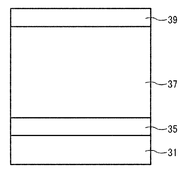
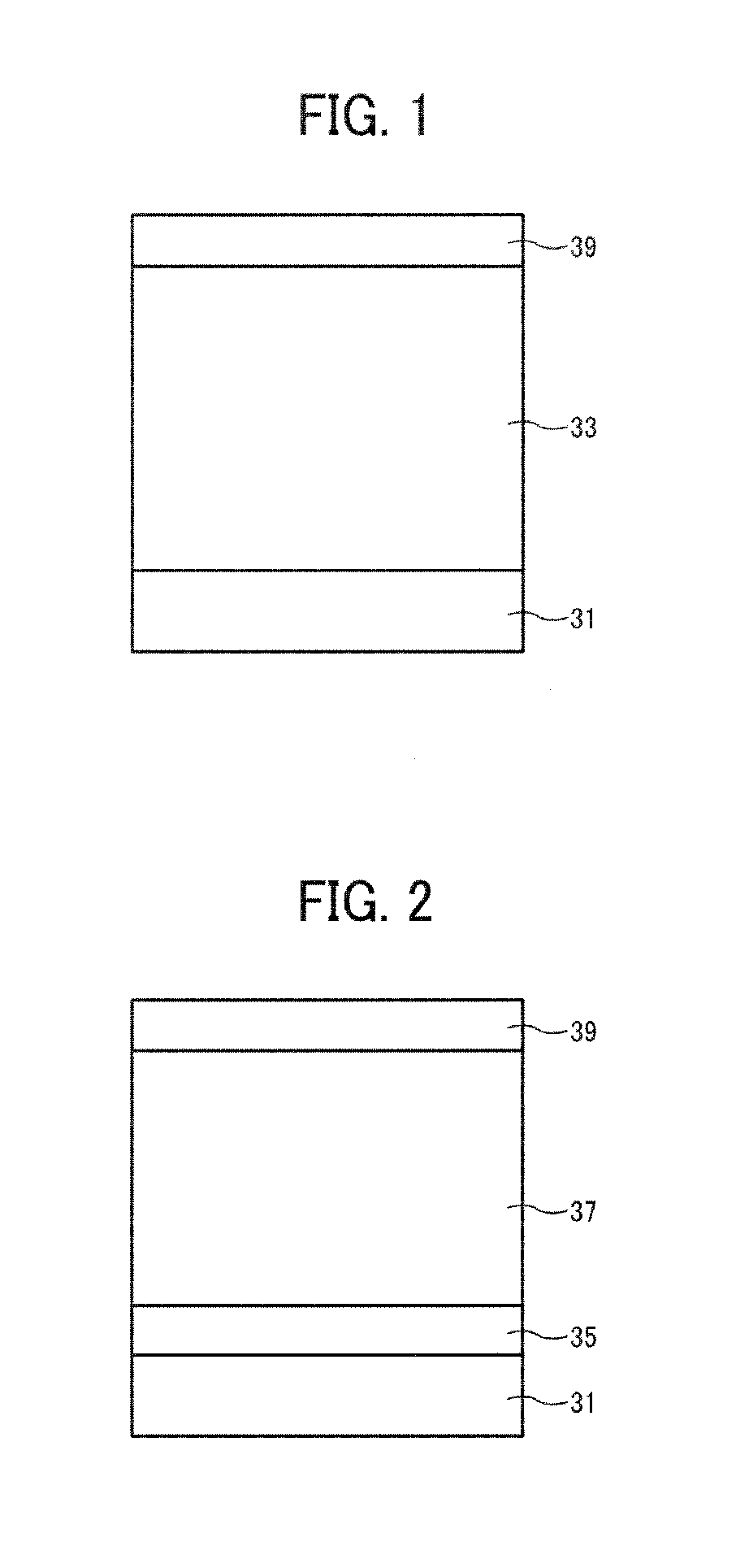
The present invention provides an improved image bearing member with a cross-linked surface layer that includes a cross-linked polymer and a specific compound. The cross-linked surface layer can be cured by irradiation with light and contains inorganic particles. The image bearing member can be charged, irradiated, developed with toner, and transferred to a transfer medium. The invention also provides an image forming method and an image forming apparatus that includes the image bearing member and various devices for charging, developing, and transferring the image. Additionally, a process cartridge detachably attachable to an image forming apparatus is provided that includes the image bearing member and various devices for charging, developing, transferring, cleaning, and neutralizing.

Problems solved by technology

In particular, the printing volume in the quick printing field has been extremely increasing and the demand for stability of the image quality has become severe.
To date, however, such an OPC remains elusive.
Although the reasons why the image bearing members having such a cross-linked surface layer fail to provide improved electrostatic stability are not completely understood, one possibility is that part of the charge transport material contained in the cross-linked surface layer is decomposed affected by the optical energy and the electron beams, with at least part of the charge transport material changing upon application of light and electron beams.
Such materials present in the cross-linked surface layer cause changes to the image bearing member over time.
As a result, image quality deteriorates sharply, thereby ending the working life of the image bearing member prematurely.
In particular, unstable voltage at irradiated portions of an image bearing member causes a serious problem for an image forming apparatus for use in the quick printing field, which requires an extremely long working life and high stability of the image bearing member.
Unstable voltage at irradiated portions occurring when a image forming operation resumes after completing a previous image forming operation is more problematic than that occurring in the middle of printing for a relatively long time.
In addition, if the voltage at irradiated portions fluctuates during printing images on several sheets or several tens of sheets, correcting the voltage is difficult, which causes a serious problem
If the voltage at irradiated portions greatly changes in one job, the image density changes, degrading image consistency.
However, it is conspicuous when printing an image pattern having little text, and moreover if it is full color, not only the image density but also the color change, which creates an extremely serious problem.
However, when the charge transport material is polymerized and cross-linked, these molecules lose freedom of movement, which degrades charge transport performance.
In such a case, these charge transport materials are easily affected by oxidized gas, which may lead to accumulation of charges, resulting in deterioration of electrostatic stability.
However, when cross-linking is performed by irradiation with electron beams or light, deterioration of the charge transport material for use in the cross-linked surface layer is not prevented.
Although successful to some extent, absorption of the light by the UV curable type charge transport material still occurs upon UV irradiation and degrades the molecules, which degrades electrostatic stability.
However, the charge transport radical polymerizable monomer and the same charge transport material having a low molecular weight also deteriorate upon irradiation with ultraviolet light, which leads to degradation of the electrostatic stability.
However, since the charge transport compound having a hydroxy group has a high affinity with water vapor, it is inferior in the environment change.
In addition, when charge transport materials having different energy levels are present in the charge transport layer, the electric characteristics deteriorate because the charge transport is inhibited among the materials, which leads to poor electrostatic stability.
However, when the binder resin non-reactivity is used, the binder resin is incompatible with the cured material produced by reaction between the monomer and the charge transport material, thereby causing phase separation in the cross-linked surface layer.
Therefore, portions having a low abrasion resistance are made locally, which may cause scarring of the surface of the image bearing member and fixation of the toner external additive and paper dust.
However, upon further investigation the present inventors have found that compounds having a triaryl amine structure exhibit changes in a portion of the charge transport structure in the cross-linked surface layer due to chemical reactions such as oxidation and dissolution upon irradiation with light, resulting in an uneven charge transport structure, an increase in residual charge, reduced chargeability, image blur over extended use, etc.
However, this is not dispersed in the cross-linked resin.
In addition, this method does not take into consideration balance with development of a three-dimensional network.

Method used


Image

  • Image bearing member and image forming method, image forming apparatus, and process cartridge using the same
  • Image bearing member and image forming method, image forming apparatus, and process cartridge using the same
  • Image bearing member and image forming method, image forming apparatus, and process cartridge using the same

Examples


example 1

[0210]Liquid application of undercoating layer having the following recipe is applied to an aluminum substrate (outer diameter: 60 mmΦ) by a dip coating method to form an undercoating layer having a thickness of 3.5 μm after drying at 130° C. for 20 minutes.

Liquid Application for Undercoating Layer

[0211]

Titanium dioxide powder (TIPAQUE CR-EL, manufactured400 partsby Ishihara Sangyo Kaisha Ltd.):Melamine resin (Super-beckamine G-821-60, manufactured by 65 partsDainippon Ink and Chemicals, Inc.):Alkyd resin (Beckolite M6401-50, manufactured by120 partsDainippon Ink and Chemicals, Inc.):2-butanone:400 parts

[0212]Liquid application for charge generating layer having the following recipe is applied to the undercoating layer formed as described above by a dip coating followed by heating and drying at 90° C. for 20 minutes to form a charge generating layer having a thickness of 0.2 μm.

Liquid Application for Charge Generating Layer

[0213]

Titanylphthalocyanine:8 partsPolyvinylbutyral (BX-1, m...

example 2

[0218]The image bearing member of Example 2 is manufactured in the same manner as in Example 1 except that 10 parts of the compound No. 3 illustrated above is used instead of 10 parts of the compound No. 2.

example 3

[0219]The image bearing member of Example 3 is manufactured in the same manner as in Example 1 except that 10 parts of the compound No. 5 illustrated above is used instead of 10 parts of the compound No. 2.


PUM


Abstract

An image bearing member having an electroconductive substrate, a photosensitive layer overlying the electroconductive layer, and a cross-linked surface layer overlying the photosensitive layer, which contains a cross-linked polymer and a first compound consisting essentially of a nitrogen atom and a phenyl group, biphenyl group, and condensed polycyclic hydrocarbon group, or a second compound consisting essentially of a nitrogen atom and hydrogen atoms, halogen atoms, alkyl groups, alkoxy groups, or aryl groups, substituted or non-substituted alkyl groups, substituted or non-substituted alkoxy groups, substituted or non-substituted aralkyl groups, substituted or non-substituted aryl group, substituted or non-substituted alkylene groups, cyano groups, nitro groups, or —OCO═CH2R16, in which R16 represents a hydrogen atom, a substituted or non-substituted alkyl group, a substituted or non-substituted alkoxy group, or a substituted or non-substituted aryl group.

Description

CROSS-REFERENCE TO RELATED APPLICATIONS[0001]This patent application is based on and claims priority pursuant to 35 U.S.C. §119 to Japanese Patent Application Nos. 2010-289463 and 2011-057519, filed on Dec. 27, 2010 and Mar. 16, 2011, respectively in the Japanese Patent Office, the entire disclosure of which is hereby incorporated herein by reference.FIELD OF THE INVENTION[0002]The present invention relates to an image bearing member and an image forming method, an image forming apparatus, and a process cartridge using the image bearing member.BACKGROUND OF THE INVENTION[0003]For example, the Carlson method is applied to forming images with electrophotography using such an image bearing member. Image formation employing this method includes electrostatic charging of the image bearing member typically by corona discharge in a dark place, forming a latent electrostatic image such as texts of a manual or a picture on the surface of the charged image bearing member, developing the forme...

Claims


Application Information

Patent Timeline
Patent Type & Authority Applications(United States)
IPC IPC(8): G03G21/16G03G15/00G03G5/04G03G13/00
CPCG03G5/0592G03G5/0614G03G5/14795G03G5/14704G03G5/14791G03G5/071G03G15/04G03G5/072
Inventor SHIMOYAMA, KEISUKEIKUNO, HIROSHITOSHINE, TETSUYAASANO, TOMOHARUKUBOSHIMA, YASUHITOTANAKA, YUUJI
Owner RICOH KK
Learn More