
Embedded capacitor substrate module

Active Publication Date: 2012-07-05
IND TECH RES INST
View PDF1 Cites 18 Cited by
  • Summary
  • Abstract
  • Description
  • Claims
  • Application Information

AI Technical Summary

Benefits of technology

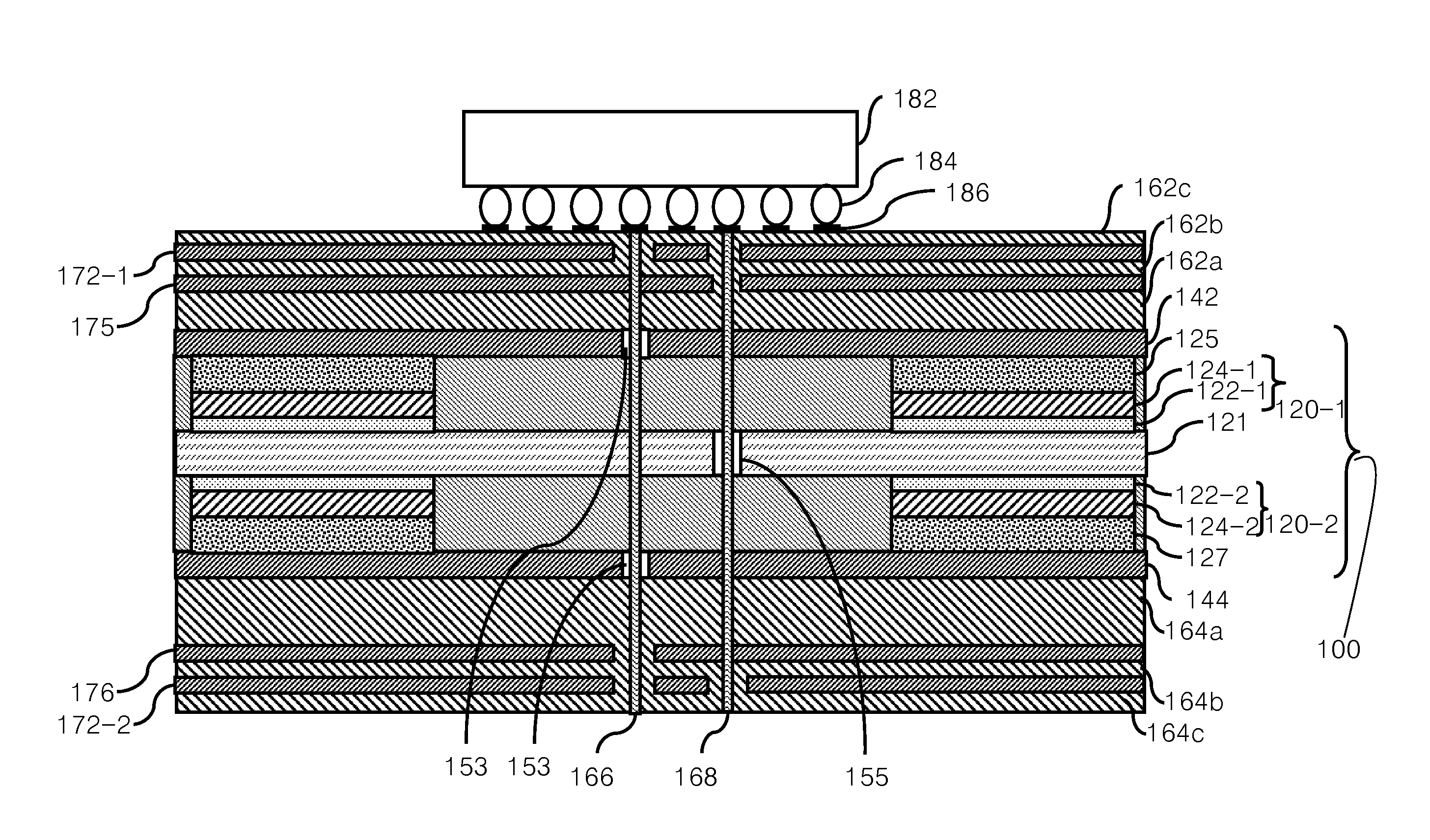
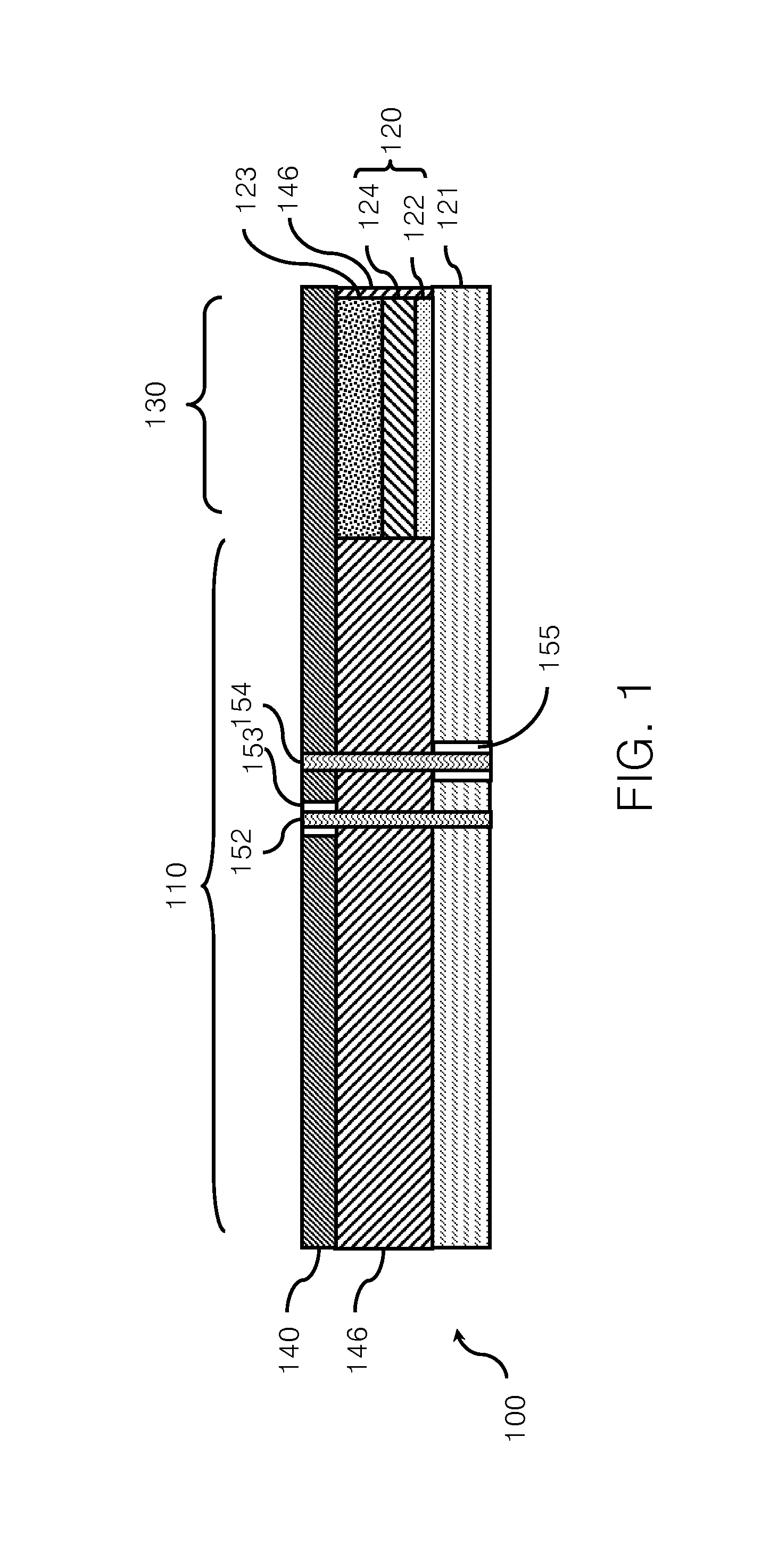
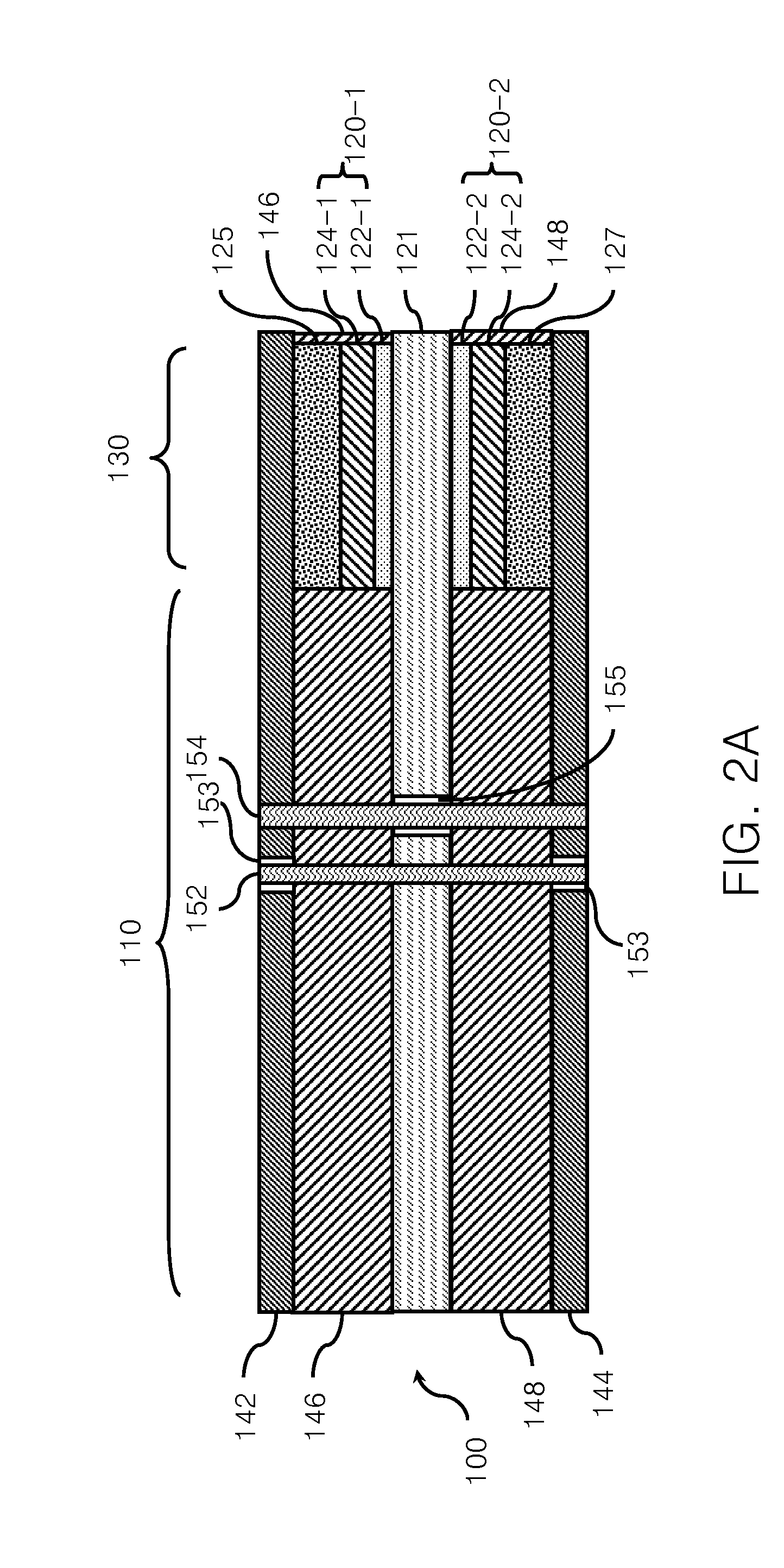
[0003]The disclosure relates to an embedded capacitor substrate module, and more particularly to an embedded capacitor substrate module using a solid electrolytic capacitor structure to increase the capacitance.
[0005]With the continuous improvement of integrated circuit (IC) process technologies, the development of portable electronic products demands for light, thin, short, small, high speed, low power consumption and multifunction features. Due to the increase of the signal transmission speed, an IC carrier board is required to transmit signals with higher frequencies, and the interference generated by synchronous switching is aggravated accordingly. To reduce noises of a power delivery system on the IC carrier board, the current high-speed IC carrier board uses several surface mounted devices (SMD) capacitors to filter the noises. Such a capacitor is generally referred to as a decoupling capacitor or a bypass capacitor, mainly for storing rated electric power and supplying the electric power when needed, thereby achieving the effects of absorbing the glitch, reducing the radio frequency (RF) noises and stabilizing the power.

Problems solved by technology

Although the technology of embedding the decoupling capacitor in the substrate is advantageous in having a low ESL, restricted by the specification of current leakage of the insulating material, the dielectric constant of the current organic insulating material is hard to exceed 100, and consequently the layers of the embedded planar capacitor must be increased upon the limited thickness and area of the substrate, so as to make the capacitance higher than 0.1 uF, which reduces the process yield and also increases the fabrication cost of the substrate.
Furthermore, the capacitance provided by the technology of embedding the capacitor in the substrate cannot meet the demand for hundreds of uF capacitance of the IC carrier board currently.
Therefore, it is a problem of the current technology of embedding the capacitor in the substrate in need of solution on how to increase the capacitance of the capacitor embedded in the substrate and increase the effective decoupling bandwidth.

Method used


Image

  • Embedded capacitor substrate module
  • Embedded capacitor substrate module
  • Embedded capacitor substrate module

Examples


Embodiment Construction

[0018]In the following detailed description, for purposes of explanation, numerous specific details are set forth in order to provide a thorough understanding of the disclosed embodiments. It will be apparent, however, that one or more embodiments may be practiced without these specific details. In other instances, well-known structures and devices are schematically shown in order to simplify the drawing.

[0019]It should be illustrated that the thickness and size of every layer and the relative ratio between all the layers in the figures of the following embodiments are exemplary in the disclosure, and may be adjusted according to practical requirements by those of ordinary skill in the art. However, the disclosure may be implemented in different forms, but is not limited to the embodiments of the disclosure. In the drawings, to make it clear, the sizes and relative sizes of the layers and regions may be amplified and / or simplified. It should be noted that when a device or a layer is...


PUM


Abstract

An embedded capacitor substrate module includes a substrate, a metal substrate and a solid electrolytic capacitor material. The solid electrolytic capacitor material is formed on the metal substrate, so as to form a solid electrolytic capacitor with the substrate. The embedded capacitor substrate module further includes an electrode lead-out region formed by extending the substrate and the metal substrate. The metal substrate serves as a first electrode, and the substrate serves as a second electrode. An insulating material is formed between the substrate and the metal substrate. Therefore, the embedded capacitor substrate module is not only advantageous in having a large capacitance as the conventional solid capacitor, but also capable of being drilled or plated and electrically connected to other circuits after being embedded in a printed circuit board.

Description

CROSS-REFERENCE TO RELATED APPLICATIONS[0001]This non-provisional application claims priority under 35 U.S.C. §119(a) on Patent Application No(s). 099146695 filed in Taiwan, R.O.C. on Dec. 29, 2010, the entire contents of which are hereby incorporated by reference.BACKGROUND[0002]1. Technical Field[0003]The disclosure relates to an embedded capacitor substrate module, and more particularly to an embedded capacitor substrate module using a solid electrolytic capacitor structure to increase the capacitance.[0004]2. Technical Art[0005]With the continuous improvement of integrated circuit (IC) process technologies, the development of portable electronic products demands for light, thin, short, small, high speed, low power consumption and multifunction features. Due to the increase of the signal transmission speed, an IC carrier board is required to transmit signals with higher frequencies, and the interference generated by synchronous switching is aggravated accordingly. To reduce noise...

Claims


Application Information

Patent Timeline
IPC IPC(8): H05K1/16
CPCH01L23/49822H01L2224/16225H05K1/162H05K3/4608H05K2201/0187H05K2201/09309H05K2203/0315H01L24/16H01L2224/16227H01L2224/16235H01L2924/14H01L2924/19041H01G9/012H01G9/15H01L23/642H05K1/0231
Inventor HSU, CHIEN-MINLEE, MIN-LINCHENG, CHENG-LIANGTSAI, LI-DUAN
Owner IND TECH RES INST
Learn More