
System for gas processing

a gas processing and gas technology, applied in the direction of liquefaction, separation processes, lighting and heating apparatus, etc., can solve the problems of additional cost and energy requirements, subsequent reduction of overall power plant efficiency, etc., to improve the overall efficiency of the power plant, and save energy consumption

Inactive Publication Date: 2012-07-12
ALSTOM TECH LTD
View PDF7 Cites 10 Cited by
  • Summary
  • Abstract
  • Description
  • Claims
  • Application Information

AI Technical Summary

Benefits of technology

[0017]The power plant with the post-combustion flue gas processing system according to the invention allows, due to the integration of an adiabatic compressor, a reduction of the total power consumption necessary for the flue gas compression. Furthermore, the adiabatic compressor without intercoolers allows a recovery of the heat from the flue gas and its use in the power plant or in a system connected with the power plant such as an industrial consumer or other consumer requiring heat. Thereby, required heat, for example for feedwater preheating, that would otherwise be extracted from the power plant can now be drawn from the compressed flue gases. The system according to the invention therefore facilitates an improvement in the overall efficiency of the power plant thus integrated with the flue gas processing system, however without an increase in number of compressor machines.
[0018]Additionally, a flue gas processing system according to the invention allows a reduction in the initial investment cost for the system. The system comprises a total of only two compression machines with two drivers and two shafts, i.e. the adiabatic, flue gas compressor on one hand and the combination of second low-pressure flue gas compressor with high-pressure CO2 multi-stage compressor, on the other hand. In spite of the addition of an adiabatic compressor, the system's total number of machines is still the same. Finally, the combination of the second low-pressure flue gas compressor and high-pressure CO2 compressor into one machine results not only in a reduction in investment cost but also allows space efficiency in the power plant construction.
[0020]In a further particular embodiment of the invention, the flue gas processing system comprises a dehydration unit arranged downstream of the second low-pressure flue gas compressor. This allows greater possibilities in the handling and use of the resulting CO2.
[0022]In an embodiment, the adiabatic flue gas compressor discharge pressure can be set to 7 to 9 bar abs. Above this pressure range the adiabatic compression would require more power consumption than the compression in an intercooled centrifugal compressor. With this discharge pressure the temperature at the discharge of the adiabatic compressor is in the range from 170 to 280° C. This allows an efficient heat recovery for instance by heating condensates from the power plant steam / water cycle through the use of a dedicated heat exchanger.
[0023]After the heat recovery, the flue gas is at a temperature of about 50° C. It is then further cooled in a second exchanger, where heat is dissipated. It is then compressed to 30 to 40 bar abs by two stages of the second low-pressure flue gas compressor, a centrifugal compressor with intercoolers. These two stages can be easily combined with the high-pressure CO2 compressor having 4 to 6 stages, for instance by the use of one integral gear compressor with 6 to 8 stages. The adiabatic compressor facilitates an improved recovery of the heat resulting from the cooling of the compressed flue gas. This can further improve the overall efficiency of a power plant integrated with this type of flue gas processing system. A further advantage of the power plant according to the invention is in that the number of flue gas compressors, these being adiabatic and centrifugal, remains constant compared to power plants of the prior art having only centrifugal compressors.

Problems solved by technology

The removal of contaminants from flue gases is not limited by technical barriers but rather by the additional cost and energy requirements and subsequent reduction in the overall power plant efficiency.

Method used


Image

  • System for gas processing
  • System for gas processing

Examples


Embodiment Construction

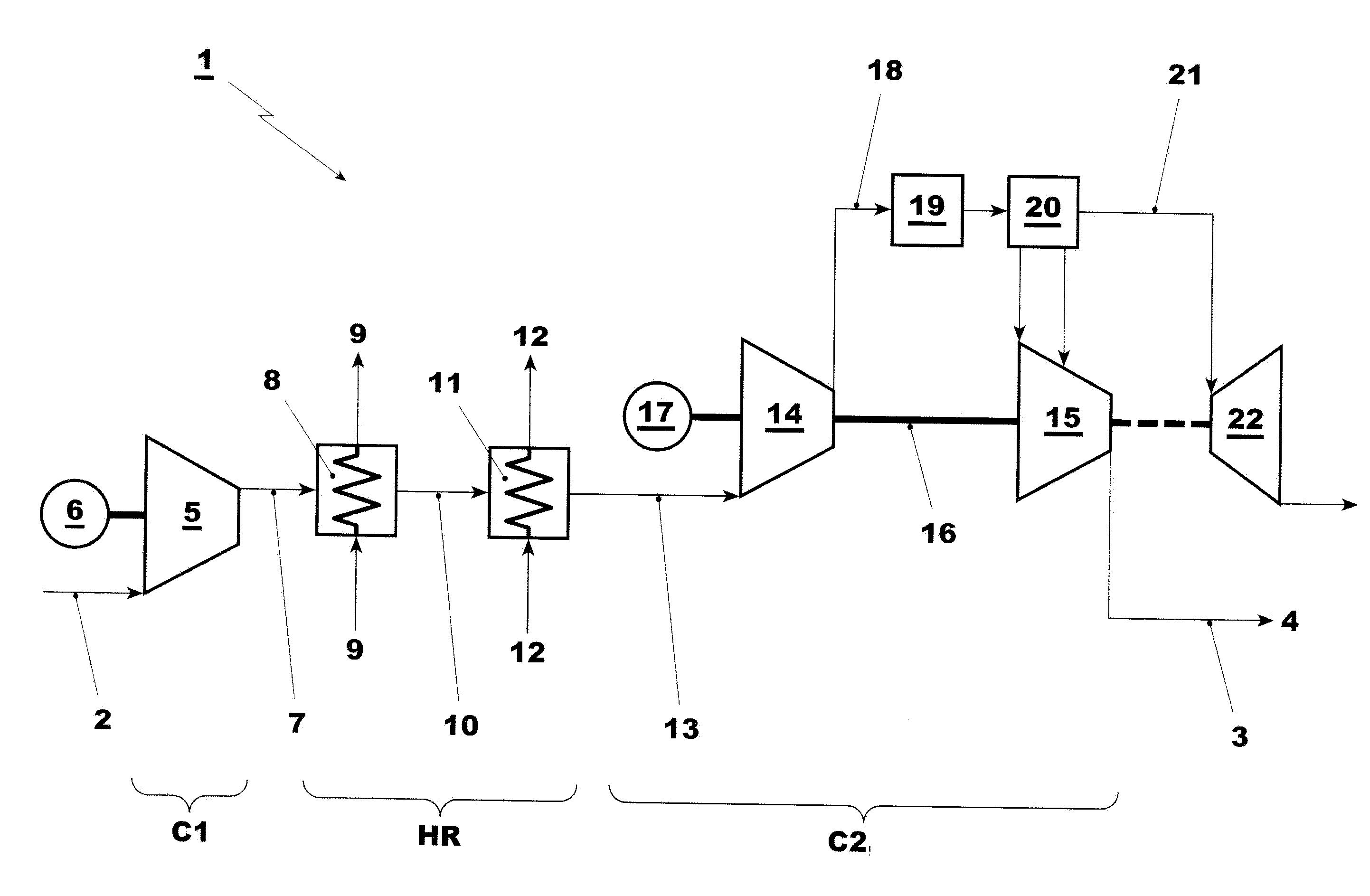
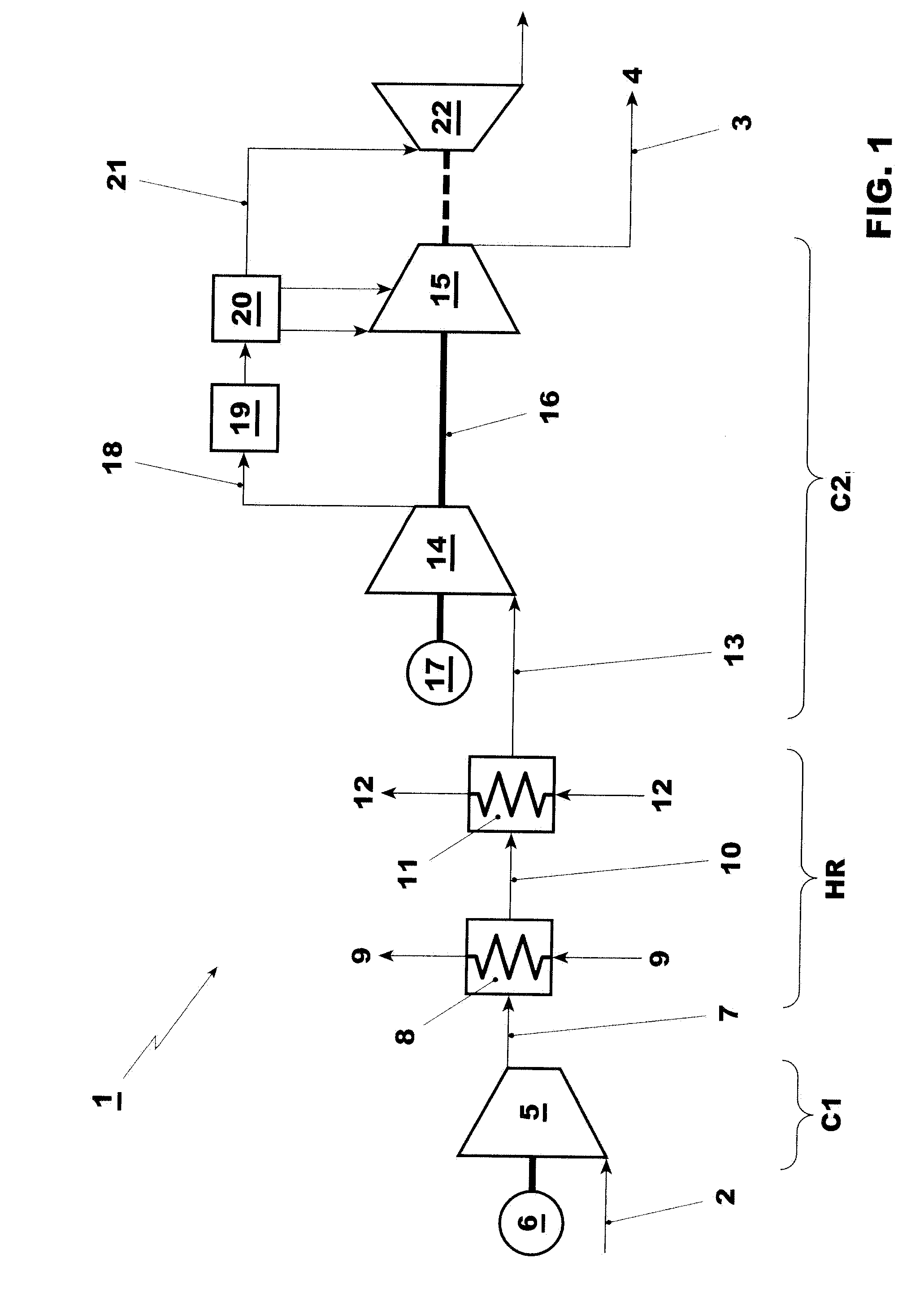
[0028]FIG. 1 shows a flue gas processing system 1 for the processing of flue gases resulting from a fossil fuel fired power plant. The power plant itself is not shown save for a line 2 directing the flue gas resulting from the combustion of fossil fuels for the generation of a working medium to drive a turbine. The processing system 1 comprises essentially a flue gas line 2, directing flue gases to a first compressor system C1, heat recovery system HR, a second compressor system C2, all arranged in series in the sequence mentioned, and a CO2-line 3 for directing the separated CO2 to a facility for further use. The flue gas line 2 leads from a power plant to the first compressor system C1, which comprises an adiabatic flue gas compressor 5. The heat recovery system HR comprises heat exchangers for the cooling of the compressed flue gases released by the compressor C1 and transfer of heat from the flue gases to the power plant. The second compressor system C2 comprises a combined mult...


PUM


Abstract

A power plant for the generation of electrical energy with a system (1) for processing flue gases resulting from a combustion of fossil fuels comprises, according to the invention, an adiabatic compressor (5) for a first low-pressure compression of the flue gases and a second multi-stage, low-pressure flue gas compression system (14) and a multi-stage, high-pressure CO2 compression system (15), where both the low-pressure flue gas compression system and the high-pressure CO2 compression systems are combined in one single machine (C2) and are arranged on one common shaft (16) driven by one common driver (17). A heat exchanger (8) facilitates an improved recovery of heat resulting from the cooling of the adiabatically compressed flue gases. The invention allows an improvement of the overall power efficiency of a power plant integrated with this processing system as well as a reduction of investment cost.

Description

TECHNICAL FIELD[0001]The present invention relates to systems for processing gas resulting from fossil fuel fired power plants for the generation of electric energy. It relates in particular to a system for gas processing to purify such gas in order to facilitate the transport and storage of carbon dioxide.BACKGROUND ART[0002]In view of reducing the emission of the greenhouse gas carbon dioxide (CO2) into the atmosphere, the flue gases of fossil fuel fired power plants for the generation of electrical energy are typically equipped with so-called CO2-capture systems. CO2 gases contained in the flue gases is first separated, then compressed, dried, and cooled and thus conditioned for permanent storage or a further use such as enhanced oil recovery. For safe transport, storage or further use, the CO2 is required to have certain qualities. For example, for enhanced oil recovery the gas is to have a CO2 concentration of at least 95%, a temperature of less than 50° C. and a pressure of 13...

Claims


Application Information

Patent Timeline
IPC IPC(8): F25J3/08F25J3/00
CPCB01D53/002Y02E20/16B01D2257/302B01D2257/404F25J3/0266F25J3/067F25J2210/70F25J2220/82F25J2230/06F25J2230/20F25J2230/30F25J2230/32F25J2230/80F25J2240/70F25J2240/90F25J2260/02Y02C10/12B01D2256/22Y02C20/40F25J3/02F25J3/06B01D53/00
Inventor GRANIER, FRANCOIS
Owner ALSTOM TECH LTD
Learn More